WIPER SWITCH INSPECTION

-
INSPECT WINDSHIELD WIPER SWITCH ASSEMBLY (for LHD)
-
Measure the resistance of the switch.
Standard resistance :
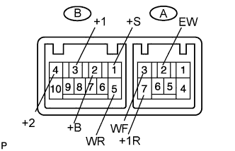
Windshield wiper switch Tester Connection Switch Condition Specified Condition B-3 (+1) - B-2 (+B) MIST Below 1 Ω B-3 (+1) - B-1 (+S) OFF Below 1 Ω B-3 (+1) - B-1 (+S) INT Below 1 Ω B-3 (+1) - B-2 (+B) LO Below 1 Ω B-4 (+2) - B-2 (+B) HI Below 1 Ω Windshield washer switch Tester Connection Switch Condition Specified Condition A-3 (WF) - A-2 (EW) OFF 10 kΩ or higher A-3 (WF) - A-2 (EW) ON Below 1 Ω Rear wiper and washer switch Tester Connection Switch Condition Specified Condition A-2 (EW) - B-5 (WR) WASH
(Rear wiper switch ON position side)
Below 1 Ω A-2 (EW) - B-5 (WR) OFF 10 kΩ or higher A-7 (+1R) - B-5 (WR) OFF 10 kΩ or higher A- 2 (EW) - A-7 (+1R) OFF 10 kΩ or higher A- 2 (EW) - A-7 (+1R) ON Below 1 Ω A-2 (EW) - B-5 (WR) WASH
(Rear wiper switch ON position side)
Below 1 Ω A-7 (+1R) - B-5 (WR) WASH
(Rear wiper switch ON position side)
Below 1 Ω A-2 (EW) - A-7 (+1R) WASH
(Rear wiper switch ON position side)
Below 1 Ω If the result is not as specified, replace the switch assembly.
-
Check the intermittent operation.
-
Connect the voltmeter's positive (+) lead to terminal B-3 (+1) and the negative (-) lead to terminal A-2 (EW).
-
Connect the battery's positive (+) lead to terminal B-2 (+B) and the negative (-) lead to terminals A-2 (EW) and B-1 (+S).
-
Turn the wiper switch to the INT position.
-
Connect the battery's positive (+) lead to terminal B-1 (+S) for 5 seconds.
-
Connect the battery's negative (-) lead to terminal B-1 (+S). Operate the intermittent wiper relay and check the voltage between terminals B-3 (+1) and A-2 (EW).
OK Refer to illustration below. 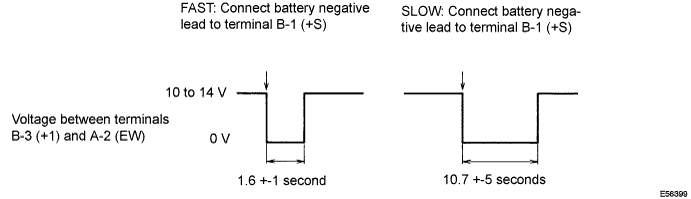
If the result is not as specified, replace the switch assembly.
-
-
Check the washer operation.
-
Turn the wiper switch OFF.
-
Connect the battery's positive (+) lead to terminal B-2 (+B) and the negative (-) lead to terminals B-1 (+S) and A-2 (EW).
-
Connect the voltmeter's positive (+) lead to terminal B-3 (+1) and the negative (-) lead to terminal A-2 (EW).
-
Turn the washer switch ON and OFF, and check the voltage between terminals B-3 (+1) and A-2 (EW).
OK Refer to illustration below. 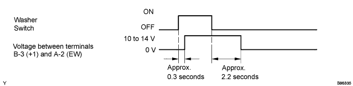
If the result is not as specified, replace the switch assembly.
-
-
-
INSPECT WINDSHIELD WIPER SWITCH ASSEMBLY (for RHD)
-
Measure the resistance of the switch.
Standard resistance :
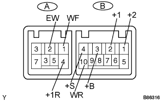
Windshield wiper switch Tester Connection Switch Condition Specified Condition B-2 (+1) - B-3 (+B) MIST Below 1 Ω B-2 (+1) - B-4 (+S) OFF Below 1 Ω B-2 (+1) - B-4 (+S) INT Below 1 Ω B-2 (+1) - B-3 (+B) LO Below 1 Ω B-1 (+2) - B-3 (+B) HI Below 1 Ω Windshield washer switch Tester Connection Switch Condition Specified Condition A-1 (WF) - A-2 (EW) OFF 10 kΩ or higher A-1 (WF) - A-2 (EW) ON Below 1 Ω Rear wiper and washer switch Tester Connection Switch Condition Specified Condition A-2 (EW) - B-10 (WR) WASH
(Rear wiper switch ON position side)
Below 1 Ω A-2 (EW) - B-10 (WR) OFF 10 kΩ or higher A-4 (+1R) - B-10 (WR) OFF 10 kΩ or higher A-2 (EW) - A-4 (+1R) OFF 10 kΩ or higher A-2 (EW) - A-4 (+1R) ON Below 1 Ω A-2 (EW) - B-10 (WR) WASH
(Rear wiper switch ON position side)
Below 1 Ω A-4 (+1R) - B-10 (WR) WASH
(Rear wiper switch ON position side)
Below 1 Ω A-2 (EW) - A-4 (+1R) WASH
(Rear wiper switch ON position side)
Below 1 Ω If the result is not as specified, replace the switch assembly.
-
Check the intermittent operation.
-
Connect the voltmeter's positive (+) lead to terminal B-2 (+1) and the negative (-) lead to terminal A-2 (EW).
-
Connect the battery's positive (+) lead to terminal B-3 (+B) and the negative (-) lead to terminals A-2 (EW) and B-4 (+S).
-
Turn the wiper switch to the INT position.
-
Connect the battery's positive (+) lead to terminal B-4 (+S) for 5 seconds.
-
Connect the battery's negative (-) lead to terminal B-4 (+S). Operate the intermittent wiper relay and check the voltage between terminals B-2 (+1) and A-2 (EW).
OK Refer to illustration below. 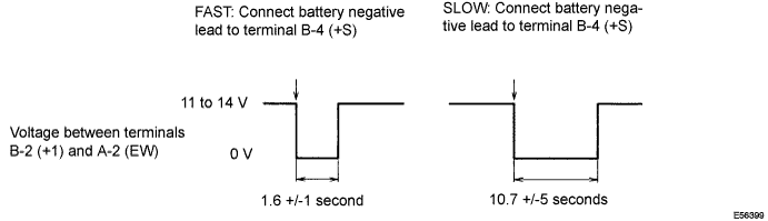
If the result is not as specified, replace the switch assembly.
-
-
Check the washer operation.
-
Turn the wiper switch OFF.
-
Connect the battery's positive (+) lead to terminal B-3 (+B) and the negative (-) lead to terminals B-4 (+S) and A-2 (EW).
-
Connect the voltmeter's positive (+) lead to terminal B-2 (+1) and the negative (-) lead to terminal A-2 (EW).
-
Turn the washer switch ON and OFF, and check the voltage between terminals B-2 (+1) and A-2 (EW).
OK Refer to illustration below. 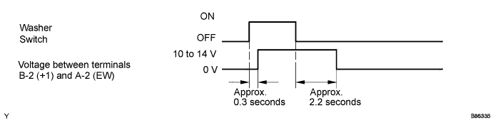
If the result is not as specified, replace the switch assembly.
-
-