STOP LIGHT SWITCH INSTALLATION

-
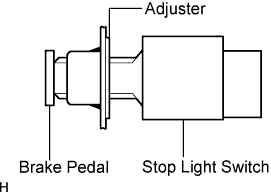
INSTALL STOP LIGHT SWITCH ASSEMBLY
-
Install the adjuster to the support.
-
Insert the switch into the adjuster until it slightly touches the pedal.
Note
Do not depress the pedal.
-
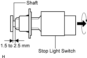
Turn the switch a quarter turn clockwise.
- Torque:
- 1.5 N*m { 15 kgf*cm, 13 in.*lbf }
Note
Do not depress the pedal.
-
Connect the switch connector to the switch.
-
Check the switch clearance.
Standard stop light switch clearance 1.5 to 2.5 mm (0.059 to 0.098 in.)
-
-
ADJUST STOP LIGHT SWITCH ASSEMBLY
-
Stop the engine. Depress the pedal several times until there is no vacuum in the booster. Then release the pedal.
-
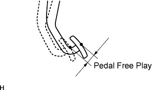
Depress the pedal until resistance is felt.
-
Check the pedal's free play by measuring the distance between the position in the previous step and the pedal's released position.
Standard pedal free play 1.0 to 6.0 mm (0.039 to 0.236 in.) If the free play is not as specified, check the switch clearance in the next step.
If the free play is as specified, proceed to the "CHECK BRAKE PEDAL RESERVE DISTANCE" procedure.
-
Check the switch clearance.
Standard stop light switch clearance 1.5 to 2.5 mm (0.059 to 0.098 in.) If the clearance is not as specified, adjust the clearance and recheck the pedal's free play.
If the clearance is as specified, troubleshoot the brake system and proceed to the "CHECK BRAKE PEDAL RESERVE DISTANCE" procedure.
-
-
CONNECT CABLE TO NEGATIVE BATTERY TERMINAL
-
PERFORM INITIALIZATION
-
Perform initialization Click here.
Note
Certain systems need to be initialized after disconnecting and reconnecting the cable from the negative (-) battery terminal.
-