LIGHTING SYSTEM Headlight Leveling ECU Power Source Circuit
DESCRIPTION
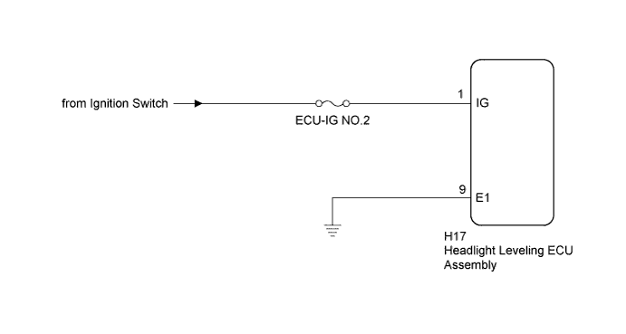
This circuit detects the state of the ignition switch, and sends it to the headlight leveling ECU.
WIRING DIAGRAM
INSPECTION PROCEDURE
Note
Inspect the fuses for circuits related to this system before performing the following inspection procedure.
Tech Tips
After replacing the headlight leveling ECU, initialization of the ECU is necessary Click here.
PROCEDURE
-
READ VALUE USING INTELLIGENT TESTER (IGNITION POWER SUPPLY)
-
Using the intelligent tester, read the Data List Click here.
HL Auto Leveling Tester Display Measurement Item/Range Normal Condition Diagnostic Note +B Ignition power supply voltage value / 0 to 19.75 V 11 to 14 V - OK The display is as specified in the normal condition column.
NG 
CHECK HARNESS AND CONNECTOR (HEADLIGHT LEVELING ECU ASSEMBLY - BATTERY AND BODY GROUND) Click here
OK 
PROCEED TO NEXT SUSPECTED AREA SHOWN IN PROBLEM SYMPTOMS TABLE Click here
-
-
CHECK HARNESS AND CONNECTOR (HEADLIGHT LEVELING ECU ASSEMBLY - BATTERY AND BODY GROUND)
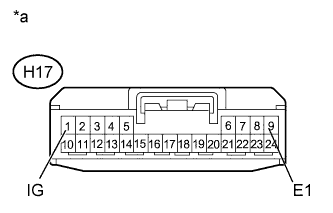
Text in Illustration *a Front view of wire harness connector
(to Headlight Leveling ECU Assembly)
-
Disconnect the H17 headlight leveling ECU connector.
-
Measure the voltage according to the value(s) in the table below.
Standard Voltage Tester Connection Switch Condition Specified Condition H17-1 (IG) - Body ground Ignition switch ON 11 to 14 V Ignition switch off Below 1 V -
Measure the resistance according to the value(s) in the table below.
Standard Resistance Tester Connection Condition Specified Condition H17-9 (E1) - Body ground Always Below 1 Ω
NG 
REPAIR OR REPLACE HARNESS OR CONNECTOR
OK
REPLACE HEADLIGHT LEVELING ECU ASSEMBLY Click here
-