LIGHTING SYSTEM Headlight Signal Circuit
DESCRIPTION
The headlight leveling ECU receives the low beam headlight on/off state information from the headlight dimmer switch to control the headlight beam level control system.
Tech Tips
Before performing troubleshooting of the automatic headlight beam level control system, check that the low beam headlights operate normally.
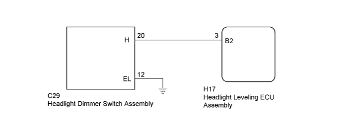
WIRING DIAGRAM
INSPECTION PROCEDURE
Tech Tips
After replacing the headlight leveling ECU, initialization of the ECU is necessary Click here.
PROCEDURE
-
READ VALUE USING INTELLIGENT TESTER (HEADLIGHT)
-
Using the intelligent tester, read the Data List Click here.
HL Auto Leveling Tester Display Measurement Item/Range Normal Condition Diagnostic Note Headlight Low Beam State Low beam headlight state / ON or OFF ON: Low beam headlights on
OFF: Low beam headlights off
- OK The display is as specified in the normal condition column.
NG 
CHECK HARNESS AND CONNECTOR (HEADLIGHT DIMMER SWITCH ASSEMBLY - HEADLIGHT LEVELING ECU ASSEMBLY AND BODY GROUND) Click here
OK 
PROCEED TO NEXT SUSPECTED AREA SHOWN IN PROBLEM SYMPTOMS TABLE Click here
-
-
CHECK HARNESS AND CONNECTOR (HEADLIGHT DIMMER SWITCH ASSEMBLY - HEADLIGHT LEVELING ECU ASSEMBLY AND BODY GROUND)
-
Disconnect the C29 headlight dimmer switch connector.
-
Disconnect the H17 headlight leveling ECU connector.
-
Measure the resistance according to the value(s) in the table below.
Standard Resistance Tester Connection Condition Specified Condition C29-20 (H) - H17-3 (B2) Always Below 1 Ω C29-12 (EL) - Body ground Always Below 1 Ω H17-3 (B2) - Body ground Always 10 kΩ or higher
NG 
REPAIR OR REPLACE HARNESS OR CONNECTOR
OK 
-
-
INSPECT HEADLIGHT DIMMER SWITCH ASSEMBLY
-
Remove the headlight dimmer switch Click here.
-
Measure the resistance according to the value(s) in the table below.
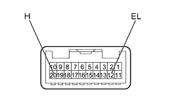
Standard Resistance Tester Connection Switch Condition Specified Condition 20 (H) - 12 (EL) Headlight dimmer switch head Below 1 Ω Headlight dimmer switch off 10 kΩ or higher
NG
REPLACE HEADLIGHT DIMMER SWITCH ASSEMBLY Click here
OK
REPLACE HEADLIGHT LEVELING ECU ASSEMBLY Click here
-