LIGHTING SYSTEM, Diagnostic DTC:B2416, B241A

| DTC Code | DTC Name |
|---|---|
| B2416 | Height Control Sensor Malfunction |
| B241A | Rear Height Control Sensor |
DESCRIPTION
The headlight leveling ECU receives signals indicating the height of the vehicle from the rear height control sensor.
| DTC Code | DTC Detection Condition | Trouble Area |
|---|---|---|
| B2416 |
|
|
| B241A |
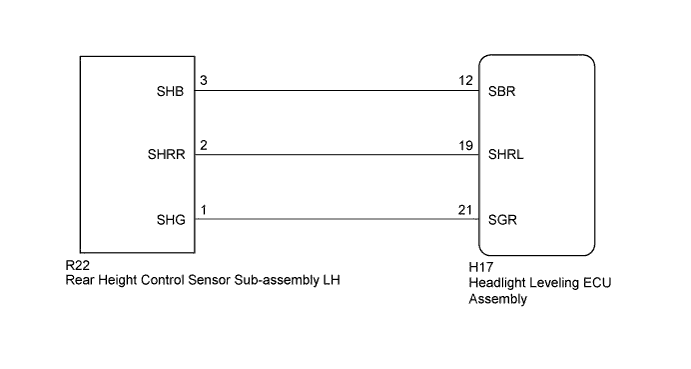
WIRING DIAGRAM
INSPECTION PROCEDURE
Tech Tips
After replacing the headlight leveling ECU and rear height control sensor, initialization of the ECU is necessary Click here.
PROCEDURE
-
CHECK FOR DTC
-
Clear the DTCs Click here.
-
Check for DTCs Click here.
OK DTC B2416 or B241A output does not occur.
NG 
READ VALUE USING INTELLIGENT TESTER (REAR HEIGHT CONTROL SENSOR) Click here
OK 
USE SIMULATION METHOD TO CHECK Click here
-
-
READ VALUE USING INTELLIGENT TESTER (REAR HEIGHT CONTROL SENSOR)
-
Using the intelligent tester, read the Data List Click here.
HL Auto Leveling Tester Display Measurement Item/Range Normal Condition Diagnostic Note Height Sens Pw Supply Val Rear height control sensor power supply value / 0 to 5 V Approximately 5.0 V - Rr Height Sens Signal Val Rear height control sensor signal value / 0 to 5 V Approximately 2.5 V (When vehicle level) The value changes according to the vehicle height. OK The display is as specified in the normal condition column.
NG
CHECK HARNESS AND CONNECTOR (HEADLIGHT LEVELING ECU ASSEMBLY - REAR HEIGHT CONTROL SENSOR SUB-ASSEMBLY LH) Click here
OK
REPLACE HEADLIGHT LEVELING ECU ASSEMBLY Click here
-
-
CHECK HARNESS AND CONNECTOR (HEADLIGHT LEVELING ECU ASSEMBLY - REAR HEIGHT CONTROL SENSOR SUB-ASSEMBLY LH)
-
Disconnect the H17 headlight leveling ECU connector.
-
Disconnect the R22 rear height control sensor connector.
-
Measure the resistance according to the value(s) in the table below.
Standard Resistance Tester Connection Condition Specified Condition H17-12 (SBR) - R22-3 (SHB) Always Below 1 Ω H17-19 (SHRL) - R22-2 (SHRR) Always Below 1 Ω H17-21 (SGR) - R22-1 (SHG) Always Below 1 Ω H17-12 (SBR) - Body ground Always 10 kΩ or higher H17-19 (SHRL) - Body ground Always 10 kΩ or higher H17-21 (SGR) - Body ground Always 10 kΩ or higher
NG 
REPAIR OR REPLACE HARNESS OR CONNECTOR
OK 
-
-
INSPECT REAR HEIGHT CONTROL SENSOR SUB-ASSEMBLY LH
-
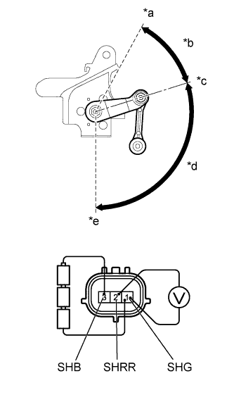
Text in Illustration *a Low (-) *b 43° *c Normal *d 105.7° *e High (+) Remove the rear height control sensor Click here.
-
Connect 3 dry cell batteries (1.5 V) in series.
-
Connect the positive (+) end of the batteries to terminal 3 (SHB) of the rear height control sensor and the negative (-) end of the batteries to terminal 1 (SHG). While slowly moving the sensor link up and down, measure the voltage between terminal 2 (SHRR) and terminal 1 (SHG).
-
Measure the voltage according to the value(s) in the table below.
Standard Voltage Tester Connection Condition Specified Condition 2 (SHRR) - 1 (SHG) High (+) 4.34 to 4.6 V Normal 3.0 to 3.3 V Low (-) 0.4 to 0.66 V Note
-
Do not apply a voltage of more than 6 V.
-
Do not drop the height control sensor. If it is dropped, replace it with a new one.
-
NG
REPLACE REAR HEIGHT CONTROL SENSOR SUB-ASSEMBLY LH Click here
OK
REPLACE HEADLIGHT LEVELING ECU ASSEMBLY Click here
-