LIGHTING SYSTEM TERMINALS OF ECU

-
CHECK HEADLIGHT LEVELING ECU (for HID Headlight)

-
Disconnect the H17 headlight leveling ECU connector.
-
Measure the voltage and resistance according to the value(s) in the table below.
Terminal No. (Symbol) Wiring Color Terminal Description Condition Specified Condition H17-1 (IG) - Body ground R-L - Body ground Ignition power supply Ignition switch off Below 1 V Ignition switch ON 11 to 14 V H17-9 (E1) - Body ground GR - Body ground Ground Always Below 1 Ω If the result is not as specified, there may be a malfunction on the wire harness side.
-
Reconnect the H17 headlight leveling ECU connector.
-
Measure the resistance and voltage according to the value(s) in the table below.
Terminal No. (Symbol) Wiring Color Terminal Description Condition Specified Condition H17-3 (B2) - H17-9 (E1) P - GR Low beam headlight signal input Low beam headlights on Below 1 V Low beam headlights off 11 to 14 V H17-5 (SPDL) - H17-9 (E1) V - GR Initialization signal input Terminal LVL and terminal CG of DLC3 connected Below 1 V Terminal LVL and terminal CG of DLC3 not connected 4.5 to 5.5 V H17-6 (WNG) - H17-9 (E1) B-L - GR Warning indicator drive output Warning indicator on Below 1 V Warning indicator off 11 to 14 V H17-10 (RH+) - H17-9 (E1) R - GR Leveling motor RH power supply Ignition switch off Below 1 V Ignition switch ON 11 to 14 V H17-11 (LH+) - H17-9 (E1) Y - GR Leveling motor LH power supply Ignition switch off Below 1 V Ignition switch ON 11 to 14 V H17-12 (SBR) - H17-21 (SGR) B - G Rear height control sensor power supply Ignition switch off Below 1 V Ignition switch ON 4.75 to 5.25 V H17-16 (SPDR) - H17-9 (E1) L - GR Vehicle speed signal input Vehicle is driven at approximately 20 km/h (12 mph) Pulse generation
(See waveform 1)
H17-17 (RHE) - H17-9 (E1) LG - GR Leveling motor RH operation signal input With low beam headlights on, vehicle height not changed Below 1 V With low beam headlights on, vehicle height changed and maintained for more than 3 seconds 1.0 to 14.4 V H17-18 (LHE) - H17-9 (E1) W - GR Leveling motor LH operation signal input With low beam headlights on, vehicle height not changed Below 1 V With low beam headlights on, vehicle height changed and maintained for more than 3 seconds 1.0 to 14.4 V H17-19 (SHRL) - H17-21 (SGR) L - G Rear height control sensor signal input Ignition switch off Below 1 V Ignition switch ON 0.5 to 4.5 V H17-21 (SGR) - H17-9 (E1) G - GR Rear height control sensor ground Always Below 1 Ω H17-23 (RH-) - H17-9 (E1) B-O - GR Leveling motor RH ground Always Below 1 Ω H17-24 (LH-) - H17-9 (E1) GR - GR Leveling motor LH ground Always Below 1 Ω If the result is not as specified, the headlight leveling ECU may have a malfunction.
-
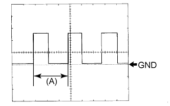
Waveform 1
Item Content Terminal No. (Symbol) H17-16 (SPDR) - H17-9 (E1) Tool setting 5 V/DIV., 20 ms./DIV. Condition Vehicle is driven at approximately 20 km/h (12 mph) Tech Tips
When the system is functioning normally, one wheel revolution generates 4 pulses. As the vehicle speed increases, the width indicated by (A) in the illustration narrows.
-
-
-
CHECK AUTOMATIC LIGHT CONTROL SENSOR (for HID Headlight)

-
Disconnect the A39 automatic light control sensor connector.
-
Measure the voltage and resistance according to the value(s) in the table below.
Terminal No. (Symbol) Wiring Color Terminal Description Condition Specified Condition A39-1 (IG) - Body ground R-L - Body ground Ignition power supply Ignition switch off Below 1 V Ignition switch ON 11 to 14 V A39-2 (B) - Body ground L-Y - Body ground Battery power supply Always 11 to 14 V A39-6 (A) - Body ground P-L - Body ground Ground Headlight dimmer switch in AUTO position Below 1 Ω Headlight dimmer switch not in AUTO position 10 kΩ or higher If the result is not as specified, there may be a malfunction on the wire harness side.
-
Reconnect the A39 automatic light control sensor connector.
-
Measure the voltage according to the value(s) in the table below.
Terminal No. (Symbol) Wiring Color Terminal Description Condition Specified Condition A39-3 (CTY) - Body ground R-B - Body ground Front door courtesy light switch LH signal input Front door LH open Below 1 V Front door LH closed 11 to 14 V A39-5 (H) - Body ground GR - Body ground H-LP RLY relay drive output Ignition switch ON
Headlight dimmer switch in AUTO position
Automatic light control sensor covered with a hand
Low beam headlights come on
Below 1 V Ignition switch ON
Headlight dimmer switch in AUTO position
Automatic light control sensor exposed to ambient light
Low beam headlights turn off
11 to 14 V A39-7 (T) - Body ground LG-B - Body ground Taillight relay drive output Ignition switch ON
Headlight dimmer switch in AUTO position
Automatic light control sensor covered with a hand
Taillights come on
Below 1 V Ignition switch ON
Headlight dimmer switch in AUTO position
Automatic light control sensor exposed to ambient light
Taillights turn off
11 to 14 V If the result is not as specified, the automatic light control sensor may have a malfunction.
-