CRUISE CONTROL MAIN SWITCH REMOVAL

-
PRECAUTION
Note
After turning the ignition switch off, waiting time may be required before disconnecting the cable from the battery terminal. Therefore, make sure to read the disconnecting the cable from the battery terminal notice before proceeding with work Click here.
-
DISCONNECT CABLE FROM NEGATIVE BATTERY TERMINAL
CAUTION:
Wait at least 90 seconds after disconnecting the cable from the negative (-) battery terminal to disable the SRS system.
Note
When disconnecting the cable, some systems need to be initialized after the cable is reconnected Click here.
-
REMOVE LOWER NO. 3 STEERING WHEEL COVER
-
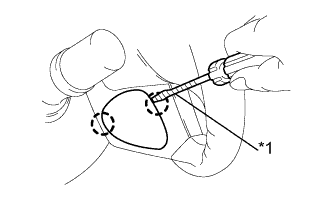
Text in Illustration *1 Protective Tape Using a screwdriver wrapped with protective tape, detach the 2 claws and remove the lower No. 3 steering wheel cover.
Tech Tips
Protective tape the screwdriver tip before use.
-
-
REMOVE LOWER NO. 2 STEERING WHEEL COVER
-
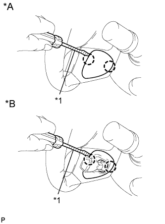
Text in Illustration *A w/o Cruise Control System *B w/ Cruise Control System *1 Protective Tape Using a screwdriver wrapped with protective tape, detach the 2 claws and remove the lower No. 2 steering wheel cover.
Tech Tips
Protective tape the screwdriver tip before use.
-
-
REMOVE STEERING PAD
-
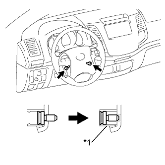
Text in Illustration *1 Screw Case Using a T30 "TORX" socket wrench, loosen the 2 screws until the groove along the screw circumference catches on the screw case.
-
Pull out the steering pad from the steering wheel as shown in the illustration. Then support the steering pad with one hand.
Note
When removing the steering pad, do not pull the airbag wire harness.
-
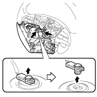
Disconnect the horn connector.
-
Disconnect the connector and remove the steering pad.
Note
When handling the airbag connector, do not damage the airbag wire harness.
-
-
REMOVE CRUISE CONTROL MAIN SWITCH
-
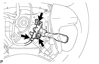
Disconnect the connector.
-
Remove the 2 screws.
-
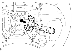
Remove the switch as shown in the illustration.
-