CRUISE CONTROL SYSTEM Cruise Control Switch Circuit
DESCRIPTION
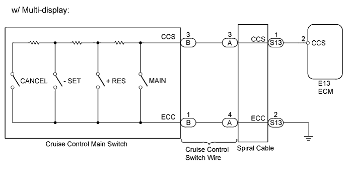
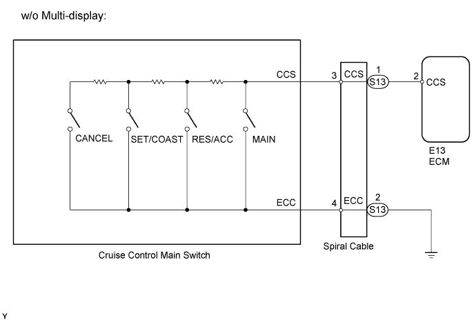
This circuit sends signals to the ECM depending on the cruise control main switch condition. The battery supplies positive (+) battery voltage to the cruise control main switch. Then terminal CCS of the ECM receives the voltage according to the switch condition.
WIRING DIAGRAM
INSPECTION PROCEDURE
PROCEDURE
-
CHECK VEHICLE CONTROL SYSTEM
-
Check vehicle system.
Result Result Proceed to w/ Multi-display A w/o Multi-display B
B 
READ VALUE USING INTELLIGENT TESTER (CRUISE CONTROL MAIN SWITCH) Click here
A 
-
-
READ VALUE USING INTELLIGENT TESTER (CRUISE CONTROL MAIN SWITCH)
-
Using the intelligent tester, read the Data List.
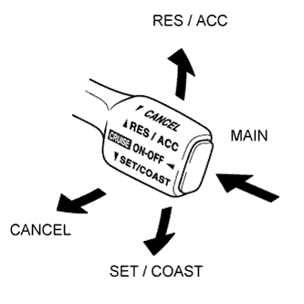
Cruise Control Tester Display Measurement Item / Range Normal Condition Diagnostic Note CCS Main SW M-CPU Cruise control main switch signal (Main CPU) / ON or OFF ON: Cruise control main switch (Main CPU) on
OFF: Cruise control main switch (Main CPU) off
- Cancel Switch CANCEL switch signal / ON or OFF ON: CANCEL switch on
OFF: CANCEL switch off
- SET/COAST Switch -SET switch signal / ON or OFF ON: -SET switch on
OFF: -SET switch off
- RES/ACC Switch +RES switch signal / ON or OFF ON: +RES switch on
OFF: +RES switch off
- OK The intelligent tester display changes according to operation of cruise control main switch.
NG
INSPECT CRUISE CONTROL MAIN SWITCH ASSEMBLY Click here
OK 
PROCEED TO NEXT CIRCUIT INSPECTION SHOWN IN PROBLEM SYMPTOMS TABLE
-
-
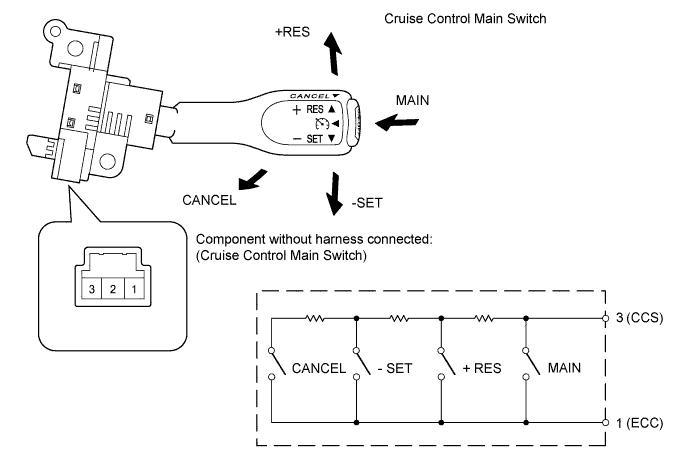
INSPECT CRUISE CONTROL MAIN SWITCH ASSEMBLY
-
Remove the cruise control main switch.
-
Measure the resistance according to the value(s) in the table below.
Standard Resistance Tester Connection Switch Condition Specified Condition 1 - 3 Neutral 10 kΩ or higher Pushed to +RES 235 to 245 Ω Pushed to -SET 617 to 643 Ω Pushed to CANCEL 1509 to 1571 Ω Main switch pushed off 10 kΩ or higher Main switch pushed on Below 1 Ω
NG 
REPLACE CRUISE CONTROL MAIN SWITCH ASSEMBLY
OK
-
-
INSPECT CRUISE CONTROL SWITCH WIRE
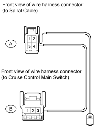
-
Remove the cruise control switch wire.
-
Measure the resistance according to the value(s) in the table below.
Standard Resistance Tester Connection Condition Specified Condition A-3 - B-3 Always Below 1 Ω A-4 - B-1
NG
REPLACE CRUISE CONTROL SWITCH WIRE
OK
-
-
INSPECT SPIRAL CABLE SUB-ASSEMBLY
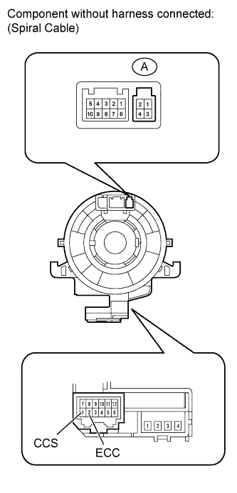
-
Remove the spiral cable.
-
Measure the resistance according to the value(s) in the table below.
Standard Resistance Tester Connection Condition Specified Condition A-3 - 1 (CCS) Always Below 1 Ω A-4 - 2 (ECC) Always Below 1 Ω
NG
REPLACE SPIRAL CABLE SUB-ASSEMBLY
OK
-
-
CHECK HARNESS AND CONNECTOR (SPIRAL CABLE - ECM AND BODY GROUND)
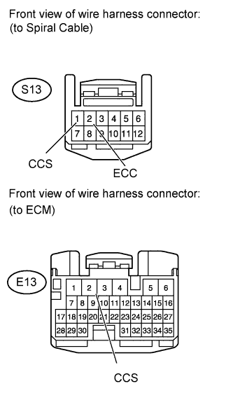
-
Disconnect the S13 spiral cable connector.
-
Disconnect the E13 ECM connector.
-
Measure the resistance according to the value(s) in the table below.
Standard Resistance for 1GR-FE Tester Connection Condition Specified Condition S13-1 (CCS) - E13-2 (CCS) Always Below 1 Ω S13-2 (ECC) - Body ground Always Below 1 Ω S13-1 (CCS) - Body ground Always 10 kΩ or higher
NG
REPAIR OR REPLACE HARNESS OR CONNECTOR
OK
PROCEED TO NEXT CIRCUIT INSPECTION SHOWN IN PROBLEM SYMPTOMS TABLE
-
-
READ VALUE USING INTELLIGENT TESTER (CRUISE CONTROL MAIN SWITCH)
-
Using the intelligent tester, read the Data List.
Cruise Control Tester Display Measurement Item / Range Normal Condition Diagnostic Note CCS Main SW M-CPU Cruise control main switch signal (Main CPU) / ON or OFF ON: Cruise control main switch (Main CPU) on
OFF: Cruise control main switch (Main CPU) off
- Cancel Switch CANCEL switch signal / ON or OFF ON: CANCEL switch on
OFF: CANCEL switch off
- SET/COAST Switch SET / COAST switch signal / ON or OFF ON: SET / COAST switch on
OFF: SET / COAST switch off
- RES/ACC Switch RES / ACC switch signal / ON or OFF ON: RES / ACC switch on
OFF: RES / ACC switch off
- OK The intelligent tester display changes according to operation of cruise control main switch.
NG
INSPECT CRUISE CONTROL MAIN SWITCH ASSEMBLY Click here
OK
PROCEED TO NEXT CIRCUIT INSPECTION SHOWN IN PROBLEM SYMPTOMS TABLE
-
-
INSPECT CRUISE CONTROL MAIN SWITCH ASSEMBLY
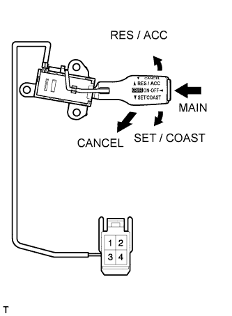
-
Remove the cruise control main switch.
-
Measure the resistance according to the value(s) in the table below.
Standard Resistance Tester Connection Switch Condition Specified Condition 3 - 4 Neutral 10 kΩ or higher Pushed to RES / ACC 235 to 245 Ω Pushed to SET / COAST 617 to 643 Ω Pushed to CANCEL 1509 to 1571 Ω Main switch pushed off 10 kΩ or higher Main switch pushed on Below 1 Ω
NG
REPLACE CRUISE CONTROL MAIN SWITCH ASSEMBLY
OK
-
-
INSPECT SPIRAL CABLE SUB-ASSEMBLY
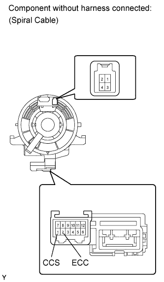
-
Remove the spiral cable.
-
Measure the resistance according to the value(s) in the table below.
Standard Resistance Tester Connection Condition Specified Condition 3 - 1 (CCS) Always Below 1 Ω 4 - 2 (ECC) Always Below 1 Ω
NG
REPLACE SPIRAL CABLE SUB-ASSEMBLY
OK
-
-
CHECK HARNESS AND CONNECTOR (SPIRAL CABLE - ECM AND BODY GROUND)
-
Disconnect the S13 spiral cable connector.
-
Disconnect the E13 ECM connector.
-
Measure the resistance according to the value(s) in the table below.
Standard Resistance for 1GR-FE Tester Connection Condition Specified Condition S13-1 (CCS) - E13-2 (CCS) Always Below 1 Ω S13-2 (ECC) - Body ground Always Below 1 Ω S13-1 (CCS) - Body ground Always 10 kΩ or higher
NG
REPAIR OR REPLACE HARNESS OR CONNECTOR
OK
PROCEED TO NEXT CIRCUIT INSPECTION SHOWN IN PROBLEM SYMPTOMS TABLE
-