CRUISE CONTROL SYSTEM Cruise Main Indicator Light Circuit
DESCRIPTION
When the cruise control main switch is turned on, the CRUISE main indicator light illuminates.
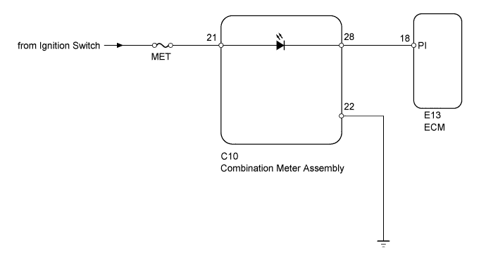
WIRING DIAGRAM
INSPECTION PROCEDURE
PROCEDURE
-
INSPECT FUSE (MET)
-
Disconnect the MET fuse from the driver side junction block.
-
Measure the resistance according to the value(s) in the table below.
Standard Resistance Tester Connection Condition Specified Condition MET fuse Always Below 1 Ω
NG 
REPLACE FUSE
OK 
-
-
CHECK HARNESS AND CONNECTOR (COMBINATION METER - ECM, BATTERY AND BODY GROUND)
-
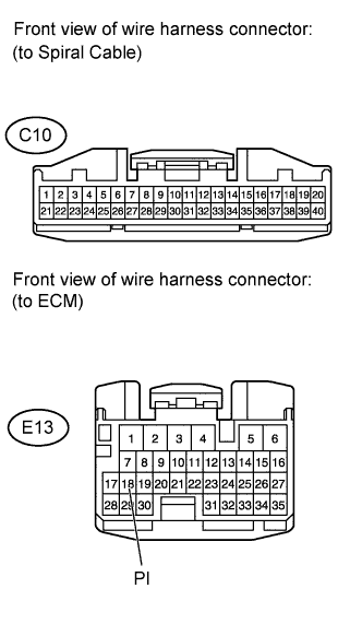
Disconnect the C10 meter connector.
-
Disconnect the E13 ECM connector.
-
Measure the voltage and resistance according to the value(s) in the table below.
Standard Voltage Tester Connection Switch Condition Specified Condition C10-21 - Body ground Ignition switch ON 11 to 14 V C10-21 - Body ground Ignition switch off Below 1 V Standard Resistance Tester Connection Condition Specified Condition C10-28 - E13-18 (PI) Always Below 1 Ω C10-28 - Body ground Always 10 kΩ or higher C10-22 - Body ground Always Below 1 Ω
NG
REPAIR OR REPLACE HARNESS OR CONNECTOR
OK 
REPLACE COMBINATION METER ASSEMBLY
-