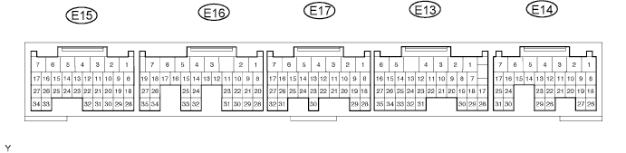
CRUISE CONTROL SYSTEM TERMINALS OF ECM

-
CHECK ECM
-
Disconnect the E14, E15 and E17 ECM connectors.
-
Measure the voltage and resistance according to the value(s) in the table below.
Terminal No. (Symbols) Wiring Color Terminal Description Condition Specified Condition E14-3 (BATT) - E17-1 (E1) L - BR Battery Always 11 to 14 V E14-9 (IGSW) - E17-1 (E1) B-O - BR IG power supply Ignition switch ON 11 to 14 V E14-9 (IGSW) - E17-1 (E1) B-O - BR IG power supply Ignition switch off Below 1 V E17-1 (E1) - Body ground BR - Body ground Ground Always Below 1 Ω E15-28 (E2) - Body ground BR - Body ground Ground Always Below 1 Ω If the result is not as specified, there may be a malfunction on the wire harness side.
-
Reconnect the E14, E15 and E17 ECM connectors.
-
Measure the voltage according to the value(s) in the table below.
Terminal No. (Symbols) Wiring Color Terminal Description Condition Specified Condition E14-15 (STP) - E17-1 (E1) G-W - BR Stop light switch input signal Ignition switch ON
Brake pedal released
Below 1 V E14-15 (STP) - E17-1 (E1) G-W - BR Stop light switch input signal Ignition switch ON
Brake pedal depressed
11 to 14 V E14-16 (ST1-) - E17-1 (E1) R-L - BR Cruise cancel input signal Ignition switch ON
Brake pedal depressed
Below 1 V E14-16 (ST1-) - E17-1 (E1) R-L - BR Cruise cancel input signal Ignition switch ON
Brake pedal released
11 to 14 V E13-2 (CCS) - E17-1 (E1) G-W - BR Cruise control main switch signal Ignition switch ON 11 to 14 V E13-2 (CCS) - E17-1 (E1) G-W - BR Cruise control main switch signal Ignition switch ON
CANCEL switch held on
6.6 to 10.1 V E13-2 (CCS) - E17-1 (E1) G-W - BR Cruise control main switch signal Ignition switch ON
(-SET)*1 (SET / COAST)*2 switch held on
4.5 to 7.1 V E13-2 (CCS) - E17-1 (E1) G-W - BR Cruise control main switch signal Ignition switch ON
(+RES)*1 (RES / ACC)*2 switch held on
2.3 to 4.0 V E13-2 (CCS) - E17-1 (E1) G-W - BR Cruise control main switch signal Ignition switch ON
Main switch on
Below 1 V E13-18 (PI) - E17-1 (E1) L-B - BR Cruise main indicator light input signal Ignition switch ON
Main switch on
Below 1 V E13-18 (PI) - E17-1 (E1) L-B - BR Cruise control main switch signal Ignition switch ON
Main switch on
11 to 14 V E13-21 (D) - E17-1 (E1)*3 G-W - BR Clutch signal Ignition switch ON
Clutch pedal released
11 to 14 V E13-21 (D) - E17-1 (E1)*3 G-W - BR Clutch signal Ignition switch ON
Clutch pedal depressed
Below 1 V E14-23 (TC) - E17-1 (E1) P-B - BR Terminal TC of DLC3 Ignition switch ON 9 to 14 V *1: w/ Multi-display
*2: w/o Multi-display
*3: for Manual Transmission
If the result is not as specified, the ECM may have a malfunction.
-