THEFT DETERRENT SYSTEM ECU Power Source Circuit
DESCRIPTION
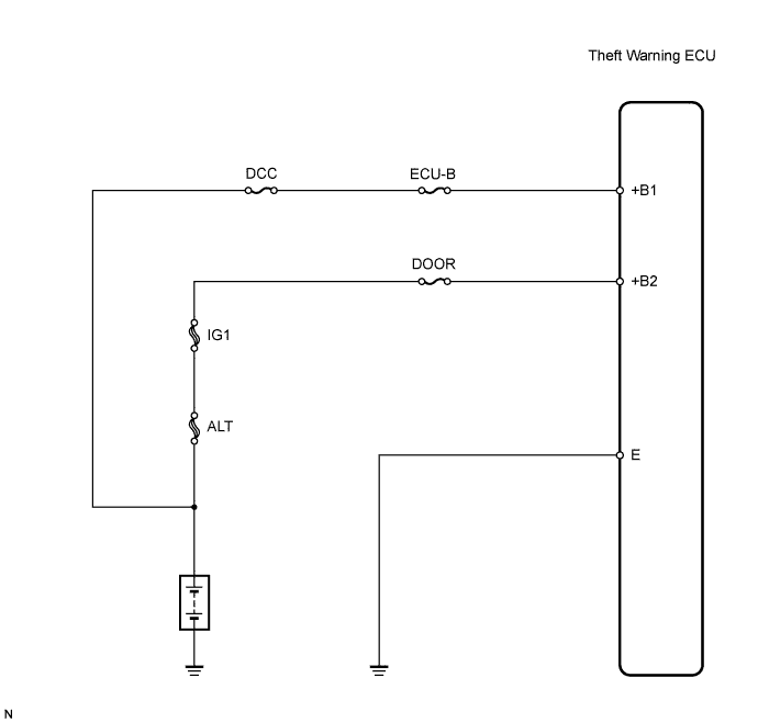
This circuit provides power to operate the theft warning ECU.
WIRING DIAGRAM
INSPECTION PROCEDURE
PROCEDURE
-
INSPECT FUSE (ECU-B, DCC, DOOR)
-
Remove the ECU-B and DCC fuses from the engine room relay block.
-
Remove the DOOR fuse from the NO. 3 relay block.
-
Measure the resistance of the fuses.
Standard resistance Below 1 Ω
NG 
REPLACE FUSE
OK 
-
-
CHECK WIRE HARNESS (THEFT WARNING ECU - BATTERY AND BODY GROUND)
-
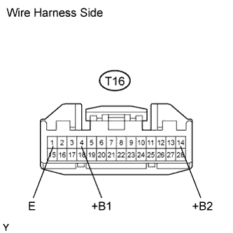
Disconnect the T16 ECU connector.
-
Measure the voltage of the wire harness side connector.
Standard voltage Tester Connection Specified Condition T16-4 (+B1) - Body ground 10 to 14 V T16-14 (+B2) - Body ground 10 to 14 V -
Measure the resistance of the wire harness side connector.
Standard resistance Tester Connection Specified Condition T16-1 (E) - Body ground Below 1 Ω
NG
REPAIR OR REPLACE HARNESS AND CONNECTOR
OK 
PROCEED TO NEXT CIRCUIT INSPECTION SHOWN IN PROBLEM SYMPTOMS TABLE
-