THEFT DETERRENT SYSTEM Driver Side Door Courtesy Switch Circuit
DESCRIPTION
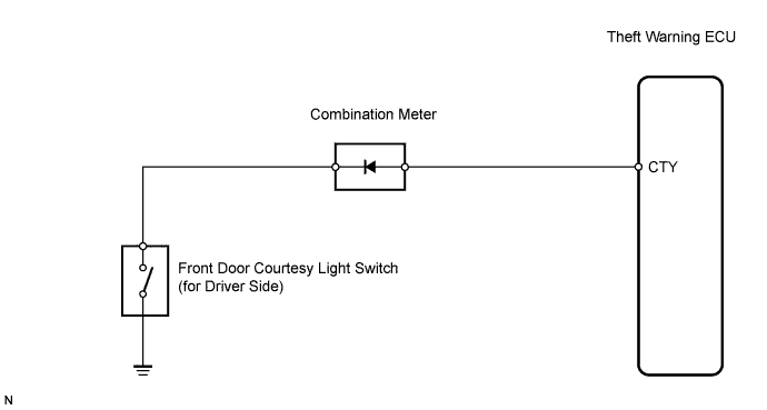
The theft warning ECU detects the condition of the front door courtesy light switch (driver side).
WIRING DIAGRAM
INSPECTION PROCEDURE
PROCEDURE
-
CHECK COMBINATION METER ASSEMBLY
-
When the driver side door is opened / closed, check that the indicator in the combination meter operates normally.
OK Indicator operates normally.
NG 
INSPECT FRONT DOOR COURTESY LIGHT SWITCH ASSEMBLY (FOR DRIVER SIDE) Click here
OK 
-
-
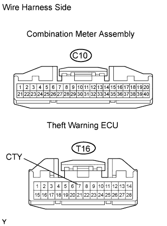
CHECK WIRE HARNESS (COMBINATION METER - THEFT WARNING ECU)
-
Disconnect the C10 meter connector.
-
Disconnect the T16 ECU connector.
-
Measure the resistance of the wire harness side connectors.
Standard resistance Tester Connection Specified Condition C10-17 - T16-7 (CTY) Below 1 Ω -
Measure the voltage of the wire harness side connectors.
Standard voltage Tester Connection Specified Condition C10-17 - Body ground 10 to 14 V
NG 
REPAIR OR REPLACE HARNESS AND CONNECTOR
OK 
PROCEED TO NEXT CIRCUIT INSPECTION SHOWN IN PROBLEM SYMPTOMS TABLE
-
-
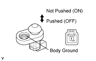
INSPECT FRONT DOOR COURTESY LIGHT SWITCH ASSEMBLY (FOR DRIVER SIDE)
-
Measure the resistance of the switch.
Standard resistance Tester Connection Switch Condition Specified Condition 1 - Body ground Not pushed (ON) Below 1 Ω 1 - Body ground Pushed (OFF) 10 kΩ or higher
NG
REPLACE FRONT DOOR COURTESY LIGHT SWITCH ASSEMBLY
OK
-
-
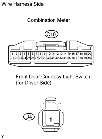
CHECK WIRE HARNESS (COMBINATION METER - FRONT DOOR COURTESY LIGHT SWITCH (FOR DRIVER SIDE))
-
Disconnect the C10 meter connector.
-
Disconnect the D4 switch connector.
-
Measure the resistance of the wire harness side connectors.
Standard resistance Tester Connection Specified Condition C10-16 - D4-1 Below 1 Ω
NG
REPAIR OR REPLACE HARNESS AND CONNECTOR
OK
REPLACE COMBINATION METER ASSEMBLY
-