THEFT DETERRENT SYSTEM Ignition Switch Circuit
DESCRIPTION
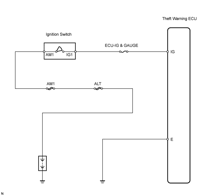
When the ignition switch is turned ON, voltage is applied to terminal IG of the theft warning ECU.
WIRING DIAGRAM
INSPECTION PROCEDURE
PROCEDURE
-
INSPECT FUSE (ECU-IG & GAUGE)
-
Remove the ECU-IG & GAUGE fuse from the instrument panel junction block.
-
Measure the resistance of the fuse.
Standard resistance Below 1 Ω
NG 
REPLACE FUSE
OK 
-
-
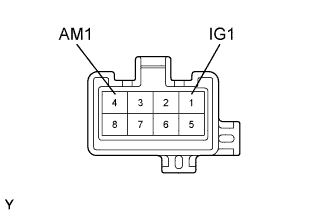
INSPECT IGNITION SWITCH ASSEMBLY
-
Disconnect the I8 switch connector
-
Measure the resistance of the ignition switch.
Standard resistance Tester Connection Switch Condition Specified Condition 1 (IG1) - 4 (AM1) OFF, ACC 10 kΩ or higher 1 (IG1) - 4 (AM1) ON, START Below 1 Ω
NG
REPLACE IGNITION SWITCH ASSEMBLY
OK
-
-
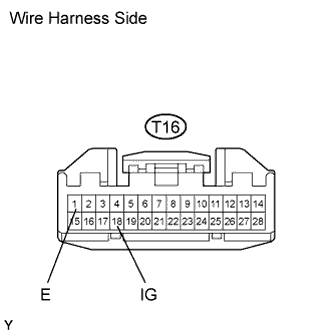
CHECK WIRE HARNESS (THEFT WARNING ECU - BATTERY AND BODY GROUND)
-
Disconnect the T16 ECU connector.
-
Measure the voltage of the wire harness side connector.
Standard voltage Tester Connection Switch Condition Specified Condition T16-18 (IG) - Body ground Ignition switch OFF Below 1 V T16-18 (IG) - Body ground Ignition switch ON 10 to 14 V -
Measure the resistance of the wire harness side connector.
Standard resistance Tester Connection Specified Condition T16-1 (E) - Body ground Below 1 Ω
NG
REPAIR OR REPLACE HARNESS AND CONNECTOR
OK 
PROCEED TO NEXT CIRCUIT INSPECTION SHOWN IN PROBLEM SYMPTOMS TABLE
-