THEFT DETERRENT SYSTEM Security Horn Circuit
DESCRIPTION
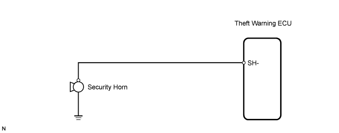
When the theft deterrent system is operating, a relay in the theft warning ECU turns ON and OFF continuously at 0.4 seconds intervals, causing the security horn to sound.
WIRING DIAGRAM
INSPECTION PROCEDURE
PROCEDURE
-
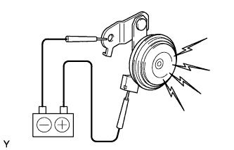
INSPECT SECURITY HORN ASSEMBLY
-
Apply battery voltage to the horn and check operation of the horn.
OK Measurement Condition Specified Condition Battery positive (+) → Terminal 1
Battery negative (-) → Horn bracket
Horn sounds
NG 
REPLACE SECURITY HORN ASSEMBLY
OK 
-
-
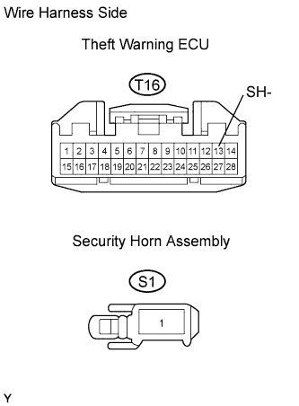
CHECK WIRE HARNESS (THEFT WARNING ECU - SECURITY HORN)
-
Disconnect the T16 ECU connector.
-
Disconnect the S1 horn connector.
-
Measure the resistance of the wire harness side connectors.
Standard resistance Tester Connection Specified Condition T16-13 (SH-) - S1-1 Below 1 Ω T16-13 (SH-) or S1-1 - Body ground 10 kΩ or higher
NG
REPAIR OR REPLACE HARNESS AND CONNECTOR
OK 
REPLACE THEFT WARNING ECU
-