THEFT DETERRENT SYSTEM Horn Circuit
DESCRIPTION
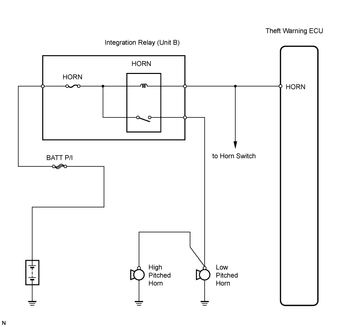
When the theft deterrent system is changed from the armed state to the alarm sounding state, the ECU turns on the HORN relay, causing the vehicle horns to sound at 0.4 seconds intervals.
WIRING DIAGRAM
INSPECTION PROCEDURE
PROCEDURE
-
CHECK HORN ASSEMBLY
-
Press the horn switch and check if the horns sound.
Result: Result Proceed to Horns sound A Horns do not sound B
B 
GO TO HORN SYSTEM
A 
-
-
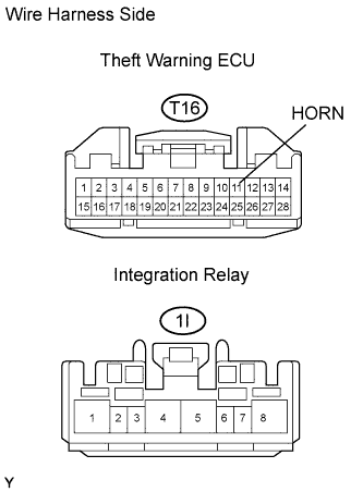
CHECK WIRE HARNESS (THEFT WARNING ECU - INTEGRATION RELAY (HORN RELAY) AND BODY GROUND)
-
Disconnect the T16 ECU connector.
-
Disconnect the 1I integration relay connector.
-
Measure the resistance of the wire harness side connectors.
Standard resistance Tester Connection Specified Condition T16-11 (HORN) - 1I-7 Below 1 Ω T16-11 (HORN) - Body ground 10 kΩ or higher
NG
REPAIR OR REPLACE HARNESS AND CONNECTOR
OK 
REPLACE THEFT WARNING ECU
-