THEFT DETERRENT SYSTEM TERMINALS OF ECU
-
CHECK THEFT WARNING ECU

-
Disconnect the T16 ECU connector.
-
Measure the voltage and resistance of the wire harness side connector.
Symbols (Terminal No.) Wiring Color Terminal Description Condition Specified Condition IG (T16-18) - E (T16-1) R-L - B-W Ignition power supply Ignition switch OFF Below 1 V IG (T16-18) - E (T16-1) R-L - B-W Ignition power supply Ignition switch ON 10 to 14 V +B1 (T16-4) - E (T16-1) L-Y - B-W +B (ECU-B) power source Always 10 to 14 V +B2 (T16-14) - E (T16-1) LG - B-W +B (DOOR) power source Always 10 to 14 V DSWH (T16-9) - E (T16-1) G-R - B-W Security courtesy switch input Engine hood fully closed Below 1 Ω DSWH (T16-9) - E (T16-1) G-R - B-W Security courtesy switch input Engine hood open 10 kΩ or higher E (T16-1) - Body ground B-W - Body ground Ground Always Below 1 Ω L2 (T16-25) - Body ground L - Body ground Door control switch (master switch) lock output Door control switch (master switch) LOCK Below 1 Ω L2 (T16-25) - Body ground L - Body ground Door control switch (master switch) lock output Door control switch (master switch) OFF 10 kΩ or higher UL3 (T16-26) - Body ground L-W - Body ground Door control switch (master switch) unlock output Door control switch (master switch) UNLOCK Below 1 Ω UL3 (T16-26) - Body ground L-W - Body ground Door control switch (master switch) unlock output Door control switch (master switch) OFF 10 kΩ or higher KSW (T16-5) - Body ground G-Y - Body ground Unlock warning switch No key in ignition key cylinder 10 kΩ or higher KSW (T16-5) - Body ground G-Y - Body ground Unlock warning switch Key inserted in ignition key cylinder Below 1 Ω
-
If the result is not as specified, there may be a malfunction on the wire harness side.
-
-
Reconnect the T16 ECU connector.
-
Measure the voltage of the connector.
Symbols (Terminal No.) Wiring Color Terminal Description Condition Specified Condition IND (T16-27) - E (T16-1) G-R - B-W Security indicator light signal output Security indicator light is flashing
(theft deterrent system is operating)
Alternating between
below 1 V and 10 to 14 V
CTY (T16-7) - E (T16-1) R-L - B-W All courtesy switch signals input Driver side, front passenger side, rear RH or rear LH door closed 10 to 14 V CTY (T16-7) - E (T16-1) R-L - B-W All courtesy switch signals input Driver side, front passenger side, rear RH or rear LH door open Below 1 V HORN (T16-11) - E (T16-1) W-R - B-W Both vehicle horn signals output
(low pitched and high pitched)
Armed state 10 to 14 V HORN (T16-11) - E (T16-1) W-R - B-W Vehicle horn signal output Alarm sounding state Below 1 V SH- (T16-13) - E (T16-1) B - B-W Security horn signal output Security horn is sounding
(theft deterrent system is in alarm sounding state)
Alternating between below 1 V and 10 to 14 V HAZD (T16-28) - E (T16-1) G-O - B-W All hazard warning light signals output Hazard warning lights are flashing
(theft deterrent system is in alarm sounding state)
Below 1 V SPD (T16-17) - E (T16-1) V-R - B-W Speed signal from combination meter Ignition switch ON, one driving wheel is rotating slowly Pulse generation
(see waveform)
-
If the result is not as specified, the ECU may have a malfunction.
-
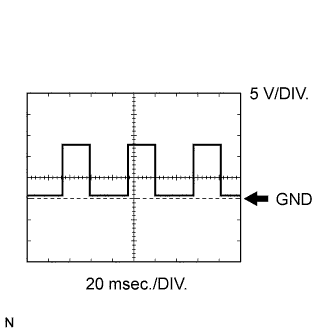
Waveform
Vehicle speed signal
Item Content Symbols (Terminal No.) SPD (T16-17) - E (T16-1) Tool Setting 5 V/DIV., 20 msec./DIV. Condition While driving vehicle Tech Tips
The wavelength becomes shorter as the vehicle speed increases.
-
-
-
CHECK INSTRUMENT PANEL JUNCTION BLOCK (INTEGRATION RELAY)

-
Disconnect the 2A, 2D and 2L junction block connectors.
-
Measure the voltage and resistance of the wire harness side connectors.
Symbols (Terminal No.) Wiring Color Terminal Description Condition Specified Condition BECU (2L-12) - GND (2D-9) L - W-B +B (BECU) power source Always 10 to 14 V GND (2D-9, 18) - Body ground W-B - Body ground Ground Always Below 1 Ω L1 (2A-4) - Body ground L - Body ground Door control switch (master switch) lock input Door control switch (master switch) LOCK 10 kΩ or higher L1 (2A-4) - Body ground L - Body ground Door control switch (master switch) lock input Door control switch (master switch) OFF Below 1 Ω UL1 (2D-4) - Body ground L-W - Body ground Door control switch (master switch) unlock input Door control switch (master switch) UNLOCK 10 kΩ or higher UL1 (2D-4) - Body ground L-W - Body ground Door control switch (master switch) unlock input Door control switch (master switch) OFF Below 1 Ω
-
If the result is not as specified, there may be a malfunction on the wire harness side.
-
-
Reconnect the 2A, 2D and 2L junction block connectors.
-
Measure the voltage of the wire harness side connectors.
Symbols (Terminal No.) Wiring Color Terminal Description Condition Specified Condition ACT+ (2R-28) - Body ground L - Body ground Door lock motor LOCK drive output (driver side door) Door control switch (master switch) or driver side door key cylinder OFF Below 1 V ACT+ (2R-28) - Body ground L - Body ground Door lock motor LOCK drive output (driver side door) Door control switch (master switch) or driver side door key cylinder LOCK 10 to 14 V ACT- (2R-27) - Body ground L-Y - Body ground Door lock motor UNLOCK drive output (driver side door) Door control switch (master switch) or driver side door key cylinder OFF Below 1 V ACT- (2R-27) - Body ground L-Y - Body ground Door lock motor UNLOCK drive output (driver side door) Door control switch (master switch) or driver side door key cylinder UNLOCK 10 to 14 V DCTY (2O-27) - Body ground R-B - Body ground Driver side courtesy switch input Driver side door closed 10 to 14 V DCTY (2O-27) - Body ground R-B - Body ground Driver side courtesy switch input Driver side door open Below 1 V
-
If the result is not as specified, there may be a malfunction in the junction block (relay).
-
-