AIRBAG SYSTEM SRS Warning Light Remains ON
DESCRIPTION
The SRS warning light is located on the combination meter. When the SRS is normal, the SRS warning light illuminates for approximately 6 seconds after the ignition switch is turned from OFF to ON, and then turns OFF automatically. If there is a malfunction in the SRS, the SRS warning light illuminates to inform the driver. When terminals TC and CG of the DLC3 are connected, the DTCs are communicated through SRS warning light blinking patterns.
WIRING DIAGRAM
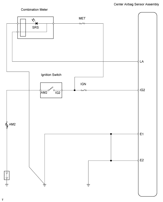
INSPECTION PROCEDURE
PROCEDURE
-
INSPECT BATTERY
-
Measure the voltage of the battery.
Standard voltage 11 to 14 V
NG 
RECHARGE OR REPLACE BATTERY
OK 
-
-
CHECK CONNECTION OF CONNECTOR
-
Disconnect the cable from the negative (-) battery terminal, and wait for at least 90 seconds.
-
Check that the connector is properly connected to the center airbag sensor.
OK Connector is connected.
NG
CONNECT CONNECTOR
OK
-
-
PREPARE FOR INSPECTION
CAUTION:
Be sure to perform the following procedures before troubleshooting to avoid unexpected airbag deployment.
-
Disconnect the connector from the center airbag sensor.
-
Disconnect the connector from the steering pad connector.
NEXT
-
-
CHECK CENTER AIRBAG SENSOR ASSEMBLY
-
Connect the cable to the negative (-) battery terminal, and wait for at least 2 seconds.
-
Turn the ignition switch ON.
-
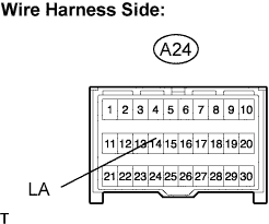
Measure the voltage and resistance of the wire harness side connector.
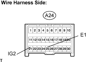
Standard voltage Tester Connection Specified Condition A24-21 (IG2) - Body ground 11 to 14 V Standard resistance Tester Connection Specified Condition A24-25 (E1) - Body ground Below 1 Ω
NG
REPAIR OR REPLACE HARNESS AND CONNECTOR
OK
-
-
CHECK COMBINATION METER ASSEMBLY (POWER SOURCE)
-
Disconnect the C27 meter connector.
-
Turn the ignition switch ON.
-
Measure the voltage of the wire harness side connector.
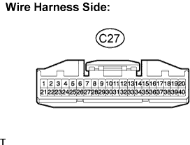
Standard voltage Tester Connection Specified Condition C27-21 - Body ground 11 to 14 V
NG
REPAIR OR REPLACE HARNESS AND CONNECTOR
OK
-
-
CHECK WIRE HARNESS (CENTER AIRBAG SENSOR ASSEMBLY - COMBINATION METER ASSEMBLY)
-
Disconnect the A24 ECU connector.
-
Disconnect the C27 meter connector.
-
Measure the resistance of the wire harness side connectors.
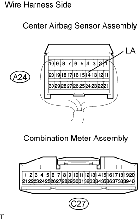
Standard resistance Tester Connection Specified Condition A24-14 (LA) - C27-20 Below 1 Ω
NG
REPAIR OR REPLACE HARNESS AND CONNECTOR
OK
-
-
CHECK SRS WARNING LIGHT OPERATION
-
Disconnect the A24 ECU connector with the C27 meter connector connected.
-
Turn the ignition switch ON.
-
Check that the warning light illuminates for 6 seconds after turning the ignition switch ON.
OK Warning light illuminates for 6 seconds after turning ignition switch ON.
NG
REPLACE COMBINATION METER ASSEMBLY
OK
-
-
CHECK CENTER AIRBAG SENSOR ASSEMBLY
-
Disconnect the A24 ECU connector.
-
Turn the ignition switch ON.
-
Measure the voltage of the wire harness side connector.
Standard voltage Tester Connection Specified Condition A24-14 (LA) - Body ground 11 to 14 V
NG
REPAIR OR REPLACE HARNESS AND CONNECTOR
OK
-
-
REPLACE CENTER AIRBAG SENSOR ASSEMBLY
-
Replace the center airbag sensor.
-
Check that the SRS warning light illuminates normally.
OK SRS warning light illuminates normally.
NG
REPLACE COMBINATION METER ASSEMBLY
OK 
END
-