REAR BLOWER CONTROL SWITCH INSPECTION

-
INSPECT COOLER CONTROL SWITCH ASSEMBLY
-
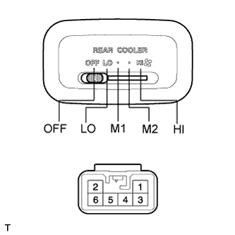
Measure the resistance of the control switch.
Standard resistance Tester Connection Switch Condition Specified Condition 5 - 4 LO Below 1 Ω 5 - 4
5 - 3
M1 Below 1 Ω 5 - 4
5 - 2
M2 Below 1 Ω 5 - 4
5 - 1
HI Below 1 Ω
-
If the result is not as specified, replace the switch assembly.
-
-
-
INSPECT COOLER(REAR) SWITCH
-
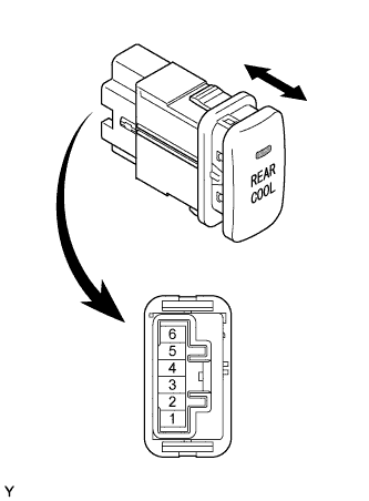
Measure the resistance of the cooler switch.
Standard resistance Tester Connection Switch Condition Specified Condition 3 - 4 ON Below 1 Ω 3 - 4 OFF 10 kΩ or higher -
Apply battery voltage to the cooler switch connector and check that the indicator light illuminates.
OK Measurement Connection Switch Condition Specified Condition Battery positive (+) → Terminal 6
Battery negative (-) → Terminal 3
ON Indicator light illuminates If the result is not as specified, replace the switch.
-