REAR COOLING UNIT INSTALLATION

-
INSTALL REAR COOLING UNIT ASSEMBLY
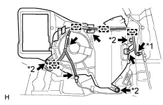
Text in Illustration *1 Bolt A *2 Bolt B
-
Install the rear cooling unit assembly with the 3 bolts labeled B.
- Torque:
- 5.4 N*m { 55 kgf*cm, 48 in.*lbf }
-
Connect the 4 connectors.
-
Attach the 4 clamps.
-
Install the body ground with the bolt labeled A.
-
-
INSTALL AIR CONDITIONING TUBE AND ACCESSORY ASSEMBLY
-
Remove the attached vinyl tape from the air conditioning tube and accessory assembly.
-
Sufficiently apply compressor oil to 2 new O-rings and the fitting surface of the air conditioning tube and accessory assembly.
Compressor oil ND-OIL 8 or equivalent -
Install the 2 O-rings to the air conditioning tube and accessory assembly.
-
Install the air conditioning tube and accessory assembly.
-
Install the 2 bolts.
- Torque:
- 5.4 N*m { 55 kgf*cm, 48 in.*lbf }
-
-
CONNECT NO. 1 COOLER COVER
-
Connect the No. 1 cooler cover with the 2 bolts.
-
Install new packing.
-
-
INSTALL QUARTER VENT DUCT ASSEMBLY RH
-
Attach the 5 claws to install the quarter vent duct assembly RH.
-
-
INSTALL REAR BUMPER COVER
-
INSTALL REAR NO. 1 SIDE AIR DUCT
-
Attach the 2 claws to install the rear No. 1 side air duct.
-
Install the 2 clips.
-
-
INSTALL REAR NO. 1 ROOF AIR DUCT
-
Install the rear No. 1 roof air duct with the 3 clips.
-
-
INSTALL REAR NO. 2 ROOF AIR DUCT
-
Install the rear No. 2 roof air duct with the 2 clips.
-
-
INSTALL REAR NO. 3 ROOF AIR DUCT
-
Install the rear No. 3 roof air duct with the 3 clips.
-
-
INSTALL REAR NO. 4 ROOF AIR DUCT
-
Install the rear No. 4 roof air duct with the 3 clips.
-
-
INSTALL REAR NO. 5 ROOF AIR DUCT
-
Install the rear No. 5 roof air duct with the 2 clips.
-
Attach the 2 clamps.
-
-
INSTALL ROOF HEADLINING ASSEMBLY
-
CONNECT CABLE TO NEGATIVE BATTERY TERMINAL
Note
When disconnecting the cable, some systems need to be initialized after the cable is reconnected Click here.
-
CHARGE REFRIGERANT
- SST
- 09985-20010 ( 09985-02130, 09985-02150, 09985-02090, 09985-02110, 09985-02010, 09985-02050, 09985-02060, 09985-02070 )
-
Perform vacuum purging using a vacuum pump.
-
Charge refrigerant HFC-134a (R134a).
Standard 750 +-30 g (26.45 +-1.05 oz.) 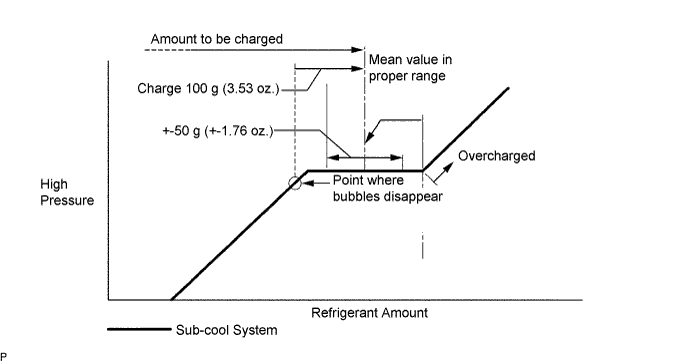
Note
-
Do not operate the cooler compressor before charging refrigerant as the cooler compressor will not work properly without any refrigerant, and will overheat.
-
Approximately 100 g (3.53 oz.) of refrigerant may need to be charged after bubbles disappear. The refrigerant amount should be checked by quantity, and not with the sight glass.
-
-
WARM UP ENGINE
-
Warm up the engine at less than 1,850 rpm for 2 minutes or more after charging refrigerant.
Note
Be sure to warm up the compressor when turning the A/C switch ON after removing and installing the cooler refrigerant lines (including the compressor), to prevent damage to the compressor.
-
-
CHECK FOR REFRIGERANT GAS LEAK
-
After recharging the refrigerant gas, check for refrigerant gas leakage using a halogen leak detector.
-
Perform the operation under these conditions:
-
Stop the engine.
-
Secure good ventilation (the gas leak detector may react to volatile gases other than refrigerant, such as evaporated gasoline or exhaust gas).
-
Repeat the test 2 or 3 times.
-
Make sure that some refrigerant remains in the refrigeration system. When compressor is off: approximately 392 to 588 kPa (4 to 6 kgf/cm2, 57 to 85 psi)
-
-
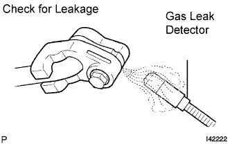
Using a gas leak detector, check the refrigerant line for leakage.
-
If a gas leak is not detected on the drain hose, remove the blower motor control (blower resistor) from the cooling unit. Insert the gas leak detector sensor into the unit and perform the test.
-
Disconnect the connector and leave the pressure switch on for approximately 20 minutes. Bring the gas leak detector close to the pressure switch and perform the test.
-