AIR CONDITIONING UNIT INSTALLATION

-
INSTALL NO. 3 AIR DUCT
-
Attach the 2 claws to install the No. 3 air duct.
-
-
TEMPORARILY INSTALL AIR CONDITIONING UNIT ASSEMBLY
-
Temporarily install the air conditioning unit assembly with the bolt and nut.
Note
-
Be sure to support the air conditioning unit assembly when installing it, because failure to do so may cause the bracket of the air conditioning unit assembly to break.
-
When installing the air conditioning unit assembly, eliminate static electricity by touching the vehicle body to prevent the components from being damaged.
-
-
-
INSTALL NO. 1 COOLER UNIT DRAIN HOSE
-
Install the No. 1 cooler unit drain hose.
-
-
INSTALL INSTRUMENT PANEL REINFORCEMENT
-
Install the instrument panel reinforcement with the 8 bolts.
- Torque:
- for bolt A
- 20 N*m { 204 kgf*cm, 15 ft.*lbf }
- for bolt B
- 18 N*m { 184 kgf*cm, 13 ft.*lbf }
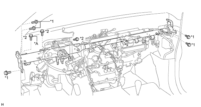
Text in Illustration *A for Manual Transmission - - *1 Bolt A *2 Bolt B -
Temporarily install the 3 bolts.
-
Connect the connectors.
-
Attach the 12 clamps.
-
Install the grommet to the vehicle body.
-
Connect the ground wires to the instrument panel reinforcement with the 2 bolts.
-
Connect the 2 connectors and attach the 2 clamps.
-
Connect the connector and attach the 3 clamps.
-
-
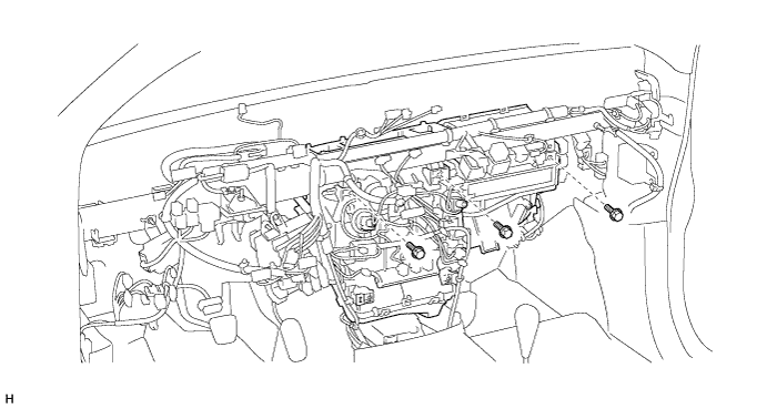
INSTALL ECM
-
for 1GR-FE:
-
for 2TR-FE:
-
-
INSTALL AIR CONDITIONING DUCT SUB-ASSEMBLY (for Automatic Air Conditioning System)
-
Attach the 2 claws to install the air conditioning duct sub-assembly.
-
-
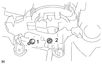
INSTALL AIR CONDITIONING UNIT ASSEMBLY
-
Tighten the 3 bolts in the order shown in the illustration.
- Torque:
- 9.8 N*m { 100 kgf*cm, 87 in.*lbf }
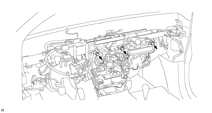
-
Temporarily install the screw.
-
Tighten the bolt and nut in the order shown in the illustration.
- Torque:
- 9.8 N*m { 100 kgf*cm, 87 in.*lbf }
-
-
INSTALL NO. 1 INSTRUMENT PANEL BRACE SUB-ASSEMBLY
-
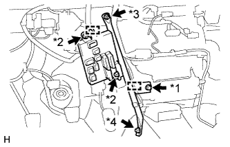
Text in Illustration *1 Screw *2 Nut A *3 Nut B *4 Bolt
-
Install the driver side junction block with the 2 nuts labeled A.
-
Connect the connectors.
-
Attach the 2 clamps.
-
Install the No. 1 instrument panel brace sub-assembly with the nut labeled B and bolt.
- Torque:
- for nut
- 9.8 N*m { 100 kgf*cm, 87 in.*lbf }
-
Tighten the screw.
- Torque:
- 9.8 N*m { 100 kgf*cm, 87 in.*lbf }
-
-
-
INSTALL NO. 4 AIR DUCT
-
Attach the 2 claws to install the No. 4 air duct.
-
-
INSTALL NO. 2 AIR DUCT
-
Attach the 2 claws to install the No. 2 air duct.
-
-
INSTALL NO. 1 AIR DUCT
-
Attach the 2 claws to install the No. 1 air duct.
-
-
INSTALL STEERING COLUMN ASSEMBLY
-
INSTALL LOWER INSTRUMENT PANEL SUB-ASSEMBLY
-
INSTALL DEFROSTER NOZZLE ASSEMBLY
-
Attach the 4 clips to install the defroster nozzle assembly.
-
-
INSTALL NO. 3 HEATER TO REGISTER DUCT
-
Attach the 4 claws to install the No. 3 heater to register duct.
-
Install the clip.
-
-
INSTALL NO. 1 HEATER TO REGISTER DUCT
-
Attach the 3 claws to install the No. 1 heater to register duct.
-
Install the clip.
-
-
INSTALL NO. 2 HEATER TO REGISTER DUCT
-
Install the No. 2 heater to register duct with the 3 clips.
-
-
INSTALL UPPER INSTRUMENT PANEL SUB-ASSEMBLY
-
CONNECT HEATER WATER OUTLET HOSE
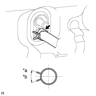
Text in Illustration *a Acceptable Range *b 2 to 40°
-
Connect the heater water outlet hose and attach the clip.
-
-
CONNECT HEATER WATER INLET HOSE
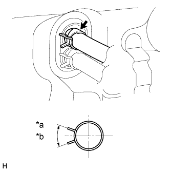
Text in Illustration *a Acceptable Range *b 2 to 40°
-
Connect the heater water inlet hose and attach the clip.
-
-
CONNECT AIR CONDITIONING TUBE AND ACCESSORY ASSEMBLY
-
Remove the vinyl tape attached to the air conditioning tube and accessory assembly.
-
Sufficiently apply compressor oil to a new O-ring and the fitting surface of the air conditioning tube and accessory assembly.
Compressor oil ND-OIL 8 or equivalent -
Install the O-ring to the air conditioning tube and accessory assembly.
-
Connect the air conditioning tube and accessory assembly.
-
-
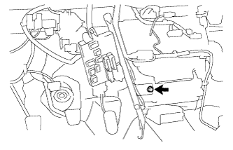
CONNECT SUCTION HOSE SUB-ASSEMBLY
-
Remove the vinyl tape attached to the suction hose sub-assembly.
-
Sufficiently apply compressor oil to a new O-ring and the fitting surface of the suction hose sub-assembly.
Compressor oil ND-OIL 8 or equivalent -
Install the O-ring to the suction hose sub-assembly.
-
Connect the suction hose sub-assembly and attach the piping clamp.
Tech Tips
After the connection, check that the claw of the piping clamp is attached.
-
Install the bolt.
- Torque:
- 5.4 N*m { 55 kgf*cm, 48 in.*lbf }
-
-
CONNECT CABLE TO NEGATIVE BATTERY TERMINAL
Note
When disconnecting the cable, some systems need to be initialized after the cable is reconnected Click here.
-
ADD ENGINE COOLANT
-
for 1GR-FE:
-
for 2TR-FE:
-
-
CHARGE REFRIGERANT
- SST
- 09985-20010 ( 09985-02130, 09985-02150, 09985-02090, 09985-02110, 09985-02010, 09985-02050, 09985-02060, 09985-02070 )
-
Perform vacuum purging using a vacuum pump.
-
Charge refrigerant HFC-134a (R134a).
Standard 750 +-30 g (26.45 +-1.05 oz.) 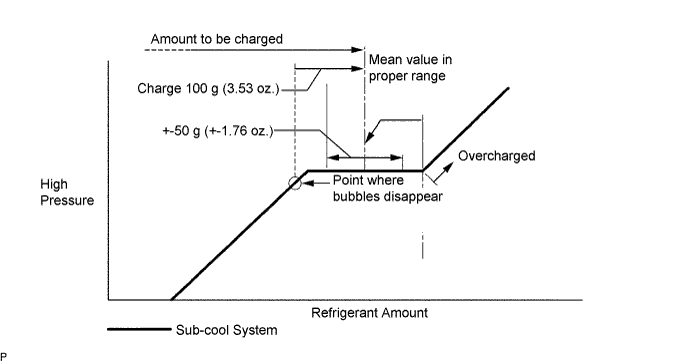
Note
-
Do not operate the cooler compressor before charging refrigerant as the cooler compressor will not work properly without any refrigerant, and will overheat.
-
Approximately 100 g (3.53 oz.) of refrigerant may need to be charged after bubbles disappear. The refrigerant amount should be checked by quantity, and not with the sight glass.
-
-
WARM UP ENGINE
-
Warm up the engine at less than 1,850 rpm for 2 minutes or more after charging refrigerant.
Note
Be sure to warm up the compressor when turning the A/C switch ON after removing and installing the cooler refrigerant lines (including the compressor), to prevent damage to the compressor.
-
-
CHECK FOR ENGINE COOLANT LEAKS
-
for 1GR-FE:
-
for 2TR-FE:
-
-
CHECK FOR REFRIGERANT GAS LEAK
-
After recharging the refrigerant gas, check for refrigerant gas leakage using a halogen leak detector.
-
Perform the operation under these conditions:
-
Stop the engine.
-
Secure good ventilation (the gas leak detector may react to volatile gases other than refrigerant, such as evaporated gasoline or exhaust gas).
-
Repeat the test 2 or 3 times.
-
Make sure that some refrigerant remains in the refrigeration system. When compressor is off: approximately 392 to 588 kPa (4 to 6 kgf/cm2, 57 to 85 psi)
-
-
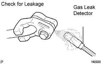
Using a gas leak detector, check the refrigerant line for leakage.
-
If a gas leak is not detected on the drain hose, remove the blower motor control (blower resistor) from the cooling unit. Insert the gas leak detector sensor into the unit and perform the test.
-
Disconnect the connector and leave the pressure switch on for approximately 20 minutes. Bring the gas leak detector close to the pressure switch and perform the test.
-
-
CHECK SRS WARNING LIGHT