AIR CONDITIONING UNIT REMOVAL

-
RECOVER REFRIGERANT FROM REFRIGERATION SYSTEM
-
Start up the engine.
-
A/C switch is ON.
-
Operate the cooler compressor with an engine speed of approximately 1,000 rpm for 5 to 6 minutes to circulate the refrigerant and collect the compressor oil remaining in each component into the cooler compressor.
-
Stop the engine.
-
Using SST, discharge the refrigerant gas.
- SST
- 09985-20010 ( 09985-02130, 09985-02150, 09985-02090, 09985-02110, 09985-02010, 09985-02050, 09985-02060, 09985-02070 )
-
-
DRAIN ENGINE COOLANT
-
for 1GR-FE:
-
for 2TR-FE:
-
-
DISCONNECT CABLE FROM NEGATIVE BATTERY TERMINAL
CAUTION:
Wait at least 90 seconds after disconnecting the cable from the negative (-) battery terminal to disable the SRS system.
Note
When disconnecting the cable, some systems need to be initialized after the cable is reconnected Click here.
-
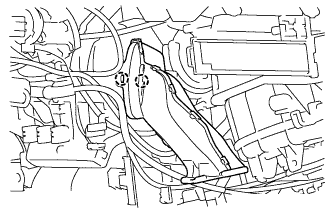
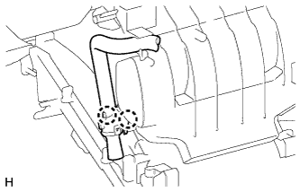
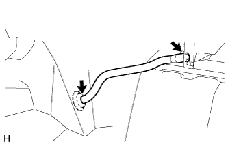
DISCONNECT SUCTION HOSE SUB-ASSEMBLY
-
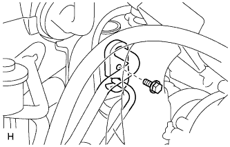
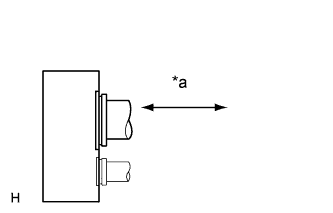
Text in Illustration *a Disconnect tube by hand Remove the bolt and disconnect the suction hose sub-assembly.
Note
-
Do not use a screwdriver or similar tool to disconnect the suction hose sub-assembly.
-
Seal the openings of the disconnected parts using vinyl tape to prevent moisture and foreign matter from entering.
-
-
Remove the O-ring from the suction hose sub-assembly.
-
-
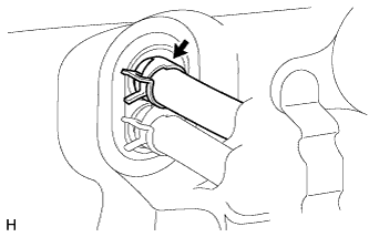
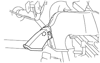
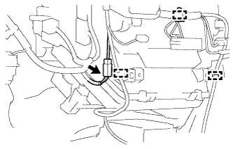
DISCONNECT AIR CONDITIONING TUBE AND ACCESSORY ASSEMBLY
-
Disconnect the air conditioning tube and accessory assembly.
Note
-
Do not use a screwdriver or similar tool to disconnect the air conditioning tube and accessory assembly.
-
Seal the openings of the disconnected parts using vinyl tape to prevent moisture and foreign matter from entering.
-
-
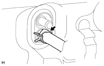
Remove the O-ring from the air conditioning tube and accessory assembly.
-
-
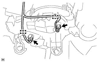
DISCONNECT HEATER WATER INLET HOSE
-
Using pliers, grip the claws of the clip and slide the clip to disconnect the heater water inlet hose.
Tech Tips
Collect the engine coolant in a container.
-
-
DISCONNECT HEATER WATER OUTLET HOSE
-
Using pliers, grip the claws of the clip and slide the clip to disconnect the heater water outlet hose.
Tech Tips
Collect the engine coolant in a container.
-
-
REMOVE UPPER INSTRUMENT PANEL SUB-ASSEMBLY
-
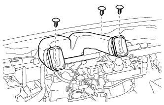
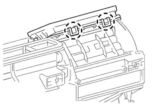
REMOVE NO. 2 HEATER TO REGISTER DUCT
-
Remove the 3 clips and No. 2 heater to register duct.
-
-
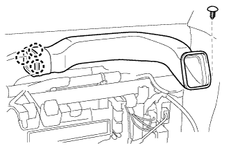
REMOVE NO. 1 HEATER TO REGISTER DUCT
-
Remove the clip.
-
Detach the 3 claws and remove the No. 1 heater to register duct.
-
-
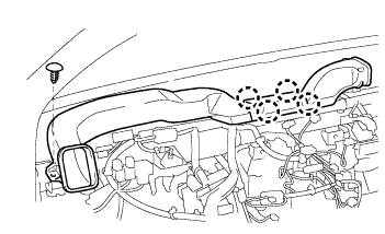
REMOVE NO. 3 HEATER TO REGISTER DUCT
-
Remove the clip.
-
Detach the 4 claws and remove the No. 3 heater to register duct.
-
-
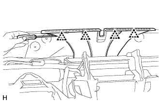
REMOVE DEFROSTER NOZZLE ASSEMBLY
-
Using a screwdriver, detach the 4 clips and remove the defroster nozzle assembly.
-
-
REMOVE LOWER INSTRUMENT PANEL SUB-ASSEMBLY
-
REMOVE STEERING COLUMN ASSEMBLY
-
REMOVE NO. 1 AIR DUCT
-
Detach the 2 claws and remove the No. 1 air duct.
-
-
REMOVE NO. 2 AIR DUCT
-
Detach the 2 claws and remove the No. 2 air duct.
-
-
REMOVE NO. 4 AIR DUCT
-
Detach the 2 claws and remove the No. 4 air duct.
-
-
REMOVE NO. 1 INSTRUMENT PANEL BRACE SUB-ASSEMBLY
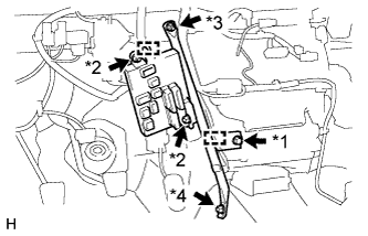
Text in Illustration *1 Screw *2 Nut A *3 Nut B *4 Bolt
-
Detach the 2 clamps and remove the 2 nuts labeled A.
-
Disconnect the connectors and remove the driver side junction block.
-
Remove the screw.
-
Remove the bolt, nut labeled B and No. 1 instrument panel brace sub-assembly.
-
-
REMOVE AIR CONDITIONING DUCT SUB-ASSEMBLY (for Automatic Air Conditioning System)
-
Detach the 2 claws and remove the air conditioning duct sub-assembly.
-
-
REMOVE ECM
-
for 1GR-FE:
-
for 2TR-FE:
-
-
REMOVE INSTRUMENT PANEL REINFORCEMENT
-
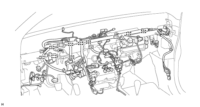
Disconnect the connector and detach the 3 clamps.
-
Detach the 2 clamps and disconnect the 2 connectors.
-
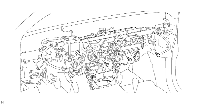
Remove the 2 bolts and disconnect the ground wires from the instrument panel reinforcement.
-
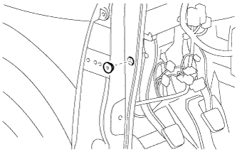
Remove the grommet from the vehicle body.
-
Detach the 12 clamps.
-
Disconnect the connectors.
-
Remove the 3 bolts.
-
for Automatic Transmission:
Remove the 7 bolts and instrument panel reinforcement.
-
for Manual Transmission:
Remove the 8 bolts and instrument panel reinforcement.
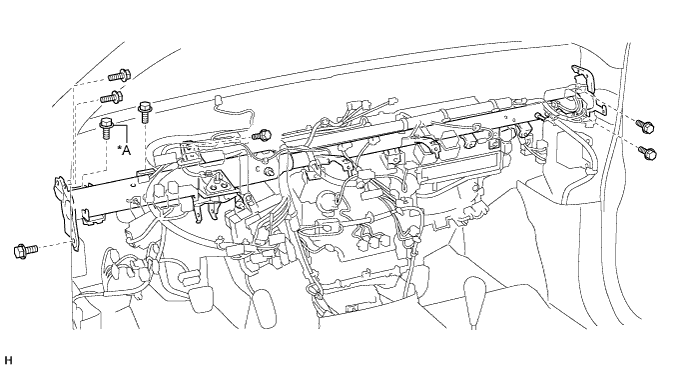
Text in Illustration *A for Manual Transmission - -
-
-
REMOVE NO. 1 COOLER UNIT DRAIN HOSE
-
Remove the No. 1 cooler unit drain hose.
-
-
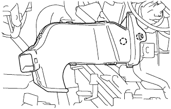
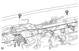
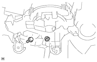
REMOVE AIR CONDITIONING UNIT ASSEMBLY
-
Remove the bolt, nut and air conditioning unit assembly.
-
-
REMOVE NO. 3 AIR DUCT
-
Detach the 2 claws and remove the No. 3 air duct.
-