AIR CONDITIONING SYSTEM (for Automatic Air Conditioning System) Air Conditioning Compressor Magnetic Clutch Circuit
DESCRIPTION
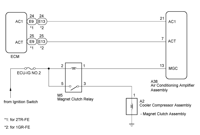
The air conditioning amplifier assembly outputs the magnet clutch on request signal to the ECM. The ECM sends a magnet clutch on permission signal to the air conditioning amplifier assembly. The air conditioning amplifier assembly turn the magnet clutch on based on the signal.
WIRING DIAGRAM
INSPECTION PROCEDURE
Note
Inspect the fuses for circuits related to this system before performing the following inspection procedure.
PROCEDURE
-
READ VALUE USING INTELLIGENT TESTER (A/C SIGNAL)
-
Use the Data List to check if the magnet clutch on request signal is functioning properly Click here.
ECM Tester Display Measurement Item/Range Normal Condition Diagnostic Note A/C Signal Magnet clutch on request signal / ON or OFF ON: A/C switch on
OFF: A/C switch off
Check this item with the engine idling and the blower switch on (LO level). OK Display is as specified in normal condition.
NG 
CHECK HARNESS AND CONNECTOR (AIR CONDITIONING AMPLIFIER - ECM) Click here
OK 
-
-
INSPECT MAGNET CLUTCH RELAY
-
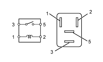
Remove the magnet clutch relay.
-
Measure the resistance according to the value(s) in the table below.
Standard Resistance Tester Connection Condition Specified Condition 3 - 5 Battery voltage is not applied to terminals 1 and 2 10 kΩ or higher Battery voltage is applied to terminals 1 and 2 Below 1 Ω
NG 
REPLACE MAGNET CLUTCH RELAY
OK
-
-
CHECK HARNESS AND CONNECTOR (AIR CONDITIONING AMPLIFIER - BATTERY)
-
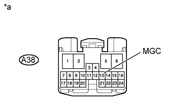
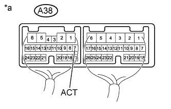
Text in Illustration *a Front view of wire harness connector
(to Air Conditioning Amplifier Assembly)
Disconnect the A38 air conditioning amplifier assembly connector.
-
Measure the voltage according to the value(s) in the table below.
Standard Voltage Tester Connection Switch Condition Specified Condition A38-13 (MGC) - Body ground Ignition switch ON 11 to 14 V Ignition switch off Below 1 V
NG
REPAIR OR REPLACE HARNESS OR CONNECTOR
OK
-
-
CHECK AIR CONDITIONING AMPLIFIER ASSEMBLY
-
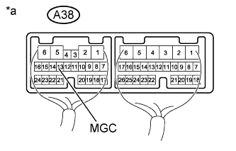
Text in Illustration *a Component with harness connected
(Air Conditioning Amplifier Assembly)
Remove the air conditioning amplifier assembly with its connectors still connected Click here.
-
Measure the voltage according to the value(s) in the table below.
Standard Voltage Tester Connection Condition Specified Condition A38-13 (MGC) - Body ground
-
Engine idling
-
Blower switch on (LO level)
-
A/C switch on
Below 1 V
-
Engine idling
-
Blower switch on (LO level)
-
A/C switch off
11 to 14 V -
NG
CHECK HARNESS AND CONNECTOR (AIR CONDITIONING AMPLIFIER - ECM) Click here
OK
-
-
INSPECT MAGNET CLUTCH ASSEMBLY
-
Remove the cooler compressor assembly.
-
for 2TR-FE: Click here.
-
for 1GR-FE: Click here.
-
-
Apply battery voltage to the magnet clutch and check operation of the magnet clutch.
OK Measurement Connection Specified Condition Battery positive (+) → Terminal 1
Battery negative (-) → Ground wire
Magnet clutch engages Result Result Proceed to OK A NG (for 2TR-FE) B NG (for 1GR-FE) C
B
REPLACE MAGNET CLUTCH ASSEMBLY Click here
C
REPLACE MAGNET CLUTCH ASSEMBLY Click here
A
-
-
CHECK HARNESS AND CONNECTOR (MAGNET CLUTCH RELAY - COOLER COMPRESSOR ASSEMBLY AND BATTERY)
-
Disconnect the A2 compressor connector.
-
Remove the magnet clutch relay.
-
Measure the voltage according to the value(s) in the table below.
Standard Voltage Tester Connection Switch Condition Specified Condition M5-5 - Body ground Ignition switch ON 11 to 14 V Ignition switch off Below 1 V -
Measure the resistance according to the value(s) in the table below.
Standard Resistance Tester Connection Condition Specified Condition M5-3 - A2-1 Always Below 1 Ω
NG
REPAIR OR REPLACE HARNESS OR CONNECTOR
OK 
PROCEED TO NEXT SUSPECTED AREA SHOWN IN PROBLEM SYMPTOMS TABLE Click here
-
-
CHECK HARNESS AND CONNECTOR (AIR CONDITIONING AMPLIFIER - ECM)
-
Disconnect the A38 air conditioning amplifier assembly connector.
-
Disconnect the E9*1 or E13*2 ECM connector.
-
*1: for 2TR-FE
-
*2: for 1GR-FE
-
-
Measure the resistance according to the value(s) in the table below.
Standard Resistance for 2TR-FE Tester Connection Condition Specified Condition A38-7 (ACT) - E9-25 (ACT) Always Below 1 Ω A38-7 (ACT) - Body ground Always 10 kΩ or higher for 1GR-FE Tester Connection Condition Specified Condition A38-7 (ACT) - E13-25 (ACT) Always Below 1 Ω A38-7 (ACT) - Body ground Always 10 kΩ or higher
NG
REPAIR OR REPLACE HARNESS OR CONNECTOR
OK
-
-
CHECK AIR CONDITIONING AMPLIFIER ASSEMBLY
-
Text in Illustration *a Component with harness connected
(Air Conditioning Amplifier Assembly)
Remove the air conditioning amplifier assembly with its connectors still connected Click here.
-
Measure the voltage according to the value(s) in the table below.
Standard Voltage Tester Connection Condition Specified Condition A38-7 (ACT) - Body ground
-
Engine idling
-
Blower switch on (LO level)
-
A/C switch on (magnet clutch on)
11 to 14 V
-
Engine idling
-
Blower switch on (LO level)
-
A/C switch off or on (magnet clutch off)
Below 1 V Result Result Proceed to OK A NG (for 2TR-FE) B NG (for 1GR-FE) C -
B
REPLACE ECM Click here
C
REPLACE ECM Click here
A
REPLACE AIR CONDITIONING AMPLIFIER ASSEMBLY Click here
-
-
CHECK HARNESS AND CONNECTOR (AIR CONDITIONING AMPLIFIER - ECM)
-
Disconnect the A38 air conditioning amplifier assembly connector.
-
Disconnect the E9*1 or E13*2 ECM connector.
-
*1: for 2TR-FE
-
*2: for 1GR-FE
-
-
Measure the resistance according to the value(s) in the table below.
Standard Resistance for 2TR-FE Tester Connection Condition Specified Condition A38-21 (AC1) - E9-24 (AC1) Always Below 1 Ω A38-21 (AC1) - Body ground Always 10 kΩ or higher for 1GR-FE Tester Connection Condition Specified Condition A38-21 (AC1) - E13-24 (AC1) Always Below 1 Ω A38-21 (AC1) - Body ground Always 10 kΩ or higher
NG
REPAIR OR REPLACE HARNESS OR CONNECTOR
OK
-
-
CHECK AIR CONDITIONING AMPLIFIER ASSEMBLY
-

Text in Illustration *a Component with harness connected
(Air Conditioning Amplifier Assembly)
Remove the air conditioning amplifier assembly with its connectors still connected Click here.
-
Measure the voltage according to the value(s) in the table below.
Standard Voltage Tester Connection Condition Specified Condition A38-21 (AC1) - Body ground
-
Engine idling
-
Blower switch on (LO level)
-
A/C switch on
Below 1 V
-
Engine idling
-
Blower switch on (LO level)
-
A/C switch off
11 to 14 V Result Result Proceed to NG A OK (for 2TR-FE) B OK (for 1GR-FE) C -
B
REPLACE ECM Click here
C
REPLACE ECM Click here
A
REPLACE AIR CONDITIONING AMPLIFIER ASSEMBLY Click here
-