AIR CONDITIONING SYSTEM (for Manual Air Conditioning System) TERMINALS OF ECU

-
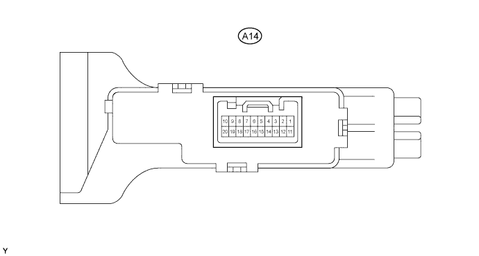
CHECK AIR CONDITIONING AMPLIFIER ASSEMBLY (w/o PTC HEATER)
-
Disconnect the A14 amplifier connector.
-
Measure the voltage and resistance of the wire harness side connector.
Symbols (Terminal No.) Wiring Color Terminal Description Condition Specified Condition IG+ (A14-10) - GND (A14-18) R-L - L Power source (IG) Ignition switch OFF Below 1 V IG+ (A14-10) - GND (A14-18) R-L - L Power source (IG) Ignition switch ON 10 to 14 V GND (A14-18) - Body ground L - Body ground Ground Always Below 1 Ω ACON (A14-4) - GND (A14-18) R-G - L A/C switch signal Ignition switch START
Blower switch ON
A/C switch OFF
Below 1 V ACON (A14-4) - GND (A14-18) R-G - L A/C switch signal Ignition switch START
Blower switch ON
A/C switch ON
10 to 14 V IND- (A14-13) - GND (A14-18) R-L - L A/C indicator light signal Ignition switch START
Blower switch ON
A/C switch OFF
Below 1 V IND- (A14-13) - GND (A14-18) R-L - L A/C indicator light signal Ignition switch START
Blower switch ON
A/C switch ON
10 to 14 V
-
If the result is not as specified, there may be a malfunction on the wire harness side.
-
-
Reconnect the A14 amplifier connector.
-
Measure the voltage and resistance of the connector.
Symbols (Terminal No.) Wiring Color Terminal Description Condition Specified Condition PSW (A14-3) - GND (A14-18) Y-B - L A/C pressure switch signal Ignition switch START
Refrigerant pressure normal: 0.18 MPa (1.9 kgf/cm2, 26 psi) to 3.03 MPa (31.0 kgf/cm2, 440 psi)
A/C switch ON
Blower switch ON
10 to 14 V PSW (A14-3) - GND (A14-18) Y-B - L A/C pressure switch signal Ignition switch START
Refrigerant pressure less than 0.18 MPa (1.9 kgf/cm2, 26 psi) or more than 3.03 MPa (31.0 kgf/cm2, 440 psi)
A/C switch ON
Blower switch ON
Below 1 V TE (A14-7) - SG-1 (A14-8) G - P A/C evaporator temperature sensor signal Ignition switch ON
Evaporator temperature is 0°C (32°F)
Temperature control knob: Max COOL
2.0 to 2.4 V TE (A14-7) - SG-1 (A14-8) G - P A/C evaporator temperature sensor signal Ignition switch ON
Evaporator temperature is 15°C (59°F)
Temperature control knob: Max COOL
1.4 to 1.8 V SG-1 (A14-8) - Body ground P - L Ground for A/C evaporator temperature sensor Always Below 1 Ω MGC (A14-1) - GND (A14-18) L-W - L Magnet clutch signal Ignition switch START
Magnet clutch is not engaged
Below 1 V MGC (A14-1) - GND (A14-18) L-W - L Magnet clutch signal Ignition switch START
Magnet clutch is engaged
10 to 14 V ACT (A14-2) - GND (A14-18) R-L - L Magnet on permit signal Ignition switch START
A/C switch OFF
Blower switch ON
Below 1 V ACT (A14-2) - GND (A14-18) R-L - L Magnet on permit signal Ignition switch START
A/C switch ON
Blower switch ON
10 to 14 V AC1 (A14-14) - GND (A14-18) Y - L Idle-up request signal Ignition switch START
Magnet clutch is not engaged
10 to 14 V AC1 (A14-14) - GND (A14-18) Y - L Idle-up request signal Ignition switch START
Magnet clutch is engaged
Below 1 V
-
If the result is not as specified, the A/C amplifier may have a malfunction.
-
-
-
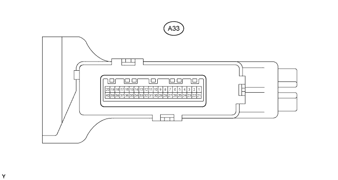
CHECK AIR CONDITIONING AMPLIFIER ASSEMBLY (w/ PTC HEATER)
-
Disconnect the A33 amplifier connector.
-
Measure the voltage and resistance of the wire harness side connector.
Symbols (Terminal No.) Wiring Color Terminal Description Condition Specified Condition IG+ (A33-20) - GND (A33-29) R-L - L Power source (IG) Ignition switch OFF Below 1V IG (A33-20) - GND (A33-29) R-L - L Power source (IG) Ignition switch ON 10 to 14 V GND (A33-29) - Body ground L - Body ground Ground Always Below 1 Ω ACON (A33-8) - GND (A33-29) R-G - L A/C switch signal Ignition switch ON
Blower switch OFF
A/C switch OFF
Below 1 V ACON (A33-8) - GND (A33-29) R-G - L A/C switch signal Ignition switch ON
Blower switch ON
A/C switch ON
10 to 14 V IND- (A33-9) - GND (A33-29) R-L - L A/C indicator light signal Ignition switch ON
Blower switch OFF
A/C switch OFF
Below 1 V IND- (A33-9) - GND (A33-29) R-L - L A/C indicator light signal Ignition switch ON
Blower switch ON
A/C switch ON
10 to 14 V BLW (MHOT) (A33-38) - GND (A33-29) R-L - L Max. HOT switch signal Ignition switch ON
Temperature control knob: Max HOT
Below 1 Ω BLW (MHOT) (A33-38) - GND (A33-29) R-L - L Max. HOT switch signal Ignition switch ON
Temperature control knob: except Max HOT
10 kΩ or higher POWHTR (A33-5) - GND (A33-29) L-O - L Heater switch signal Power heater switch ON Below 1 Ω POWHTR (A33-5) - GND (A33-29) L-O - L Heater switch signal Power heater switch OFF 10 kΩ or higher MGC (A33-19) - GND (A33-29) B - L Magnet clutch relay signal Ignition switch ON
Blower switch ON
10 to 14 V MGC (A33-19) - GND (A33-29) B - L Magnet clutch relay signal Ignition switch ON
Blower switch OFF
Below 1 V TAIL (A14-7) - GND (A14-29) G - L Light control switch signal Light control switch ON 10 to 14 V TAIL (A33-7) - GND (A33-29) G - L Light control switch signal Light control switch OFF Below 1 V
-
If the result is not as specified, there may be a malfunction on the wire harness side.
-
-
Reconnect the A33 connector.
-
Measure the voltage and resistance of the connector.
Symbols (Terminal No.) Wiring Color Terminal Description Condition Specified Condition PSW (A33-4) - GND (A33-29) Y-B - L A/C pressure switch signal Ignition switch START
Refrigerant pressure normal: 0.18 MPa (1.9 kgf/cm2, 26 psi) to 3.03 MPa (31.0 kgf/cm2, 440 psi)
A/C switch ON
Blower switch ON
10 to 14 V PSW (A33-4) - GND (A33-29) Y-B - L A/C pressure switch signal Ignition switch START
Refrigerant pressure less than 0.18 MPa (1.9 kgf/cm2, 26 psi) or more than 3.03 MPa (31.0 kgf/cm2, 440 psi)
A/C switch ON
Blower switch ON
Below 1 V TE (A33-24) - SG-1 (A33-31) G - P Evaporator temperature sensor signal Ignition switch ON
Evaporator temperature is 0°C (32°F)
Temperature control knob: MAX COOL
2.0 to 2.4 V TE (A33-24) - SG-1 (A33-31) G - P Evaporator temperature sensor signal Ignition switch ON
Evaporator temperature is 15°C (59°F)
Temperature control knob: MAX COOL
1.4 to 1.8 V SG-1 (A33-31) - Body ground P - L Ground for evaporator temperature sensor Always Below 1 Ω MGC (A33-19) - GND (A33-29) B - L Magnet clutch signal Ignition switch START
Magnet clutch is not engaged
Below 1 V MGC (A33-19) - GND (A33-29) B - L Magnet clutch signal Ignition switch START
Magnet clutch is engaged
10 to 14 V ACT (A33-39) - GND (A33-29) R-L - L Magnet on permit signal Ignition switch START
A/C switch OFF
Blower switch OFF
Below 1 V ACT (A33-39) - GND (A33-29) R-L - L Magnet on permit signal Ignition switch START
A/C switch ON
Blower switch ON
10 to 14 V AC1 (A33-35) - GND (A33-29) Y - L Idle-up request signal Ignition switch START
Magnet clutch is not engaged
10 to 14 V AC1 (A33-35) - GND (A33-29) Y - L Idle-up request signal Ignition switch START
Magnet clutch is engaged
Below 1.0 V BLW (A33-38) - GND (A33-29) R-L - L Max. HOT switch signal Ignition switch ON
Blower switch ON
temperature control knob: Max HOT
Heater switch ON
Coolant temperature 65°C (149°F)
10 to 14 V BLW (A33-38) - GND (A33-29) R-L - L Max. HOT switch signal Ignition switch ON
Blower switch ON
Temperature control knob: except Max HOT
Heater switch OFF
Coolant temperature 65°C (149°F)
Below 1 V HEAT (A33-5) - GND (A33-29) L-O - L Heater switch input signal Ignition switch ON
Blower switch ON
temperature control knob: Max HOT
Heater switch ON
Coolant temperature 65°C (149°F)
Below 1 V HEAT (A33-5) - GND (A33-29) L-O - L Heater switch input signal Ignition switch ON
Blower switch ON
Temperature control knob: except Max HOT
Heater switch OFF
Coolant temperature 65°C (149°F)
10 to 14 V SWIN (A33-15) - GND (A33-29) P - L Heater switch indicator light signal Ignition switch ON
Blower switch ON
temperature control knob: Max HOT
Heater switch ON
Coolant temperature 65°C (149°F)
Below 1 V SWIN (A33-15) - GND (A33-29) P - L Heater switch indicator light signal Ignition switch ON
Blower switch ON
Temperature control knob: except Max HOT
Heater switch OFF
Coolant temperature 65°C (149°F)
10 to 14 V PTCR (A33-26) - GND (A33-29) L-W - L Heater switch output signal Ignition switch ON
Blower switch ON
temperature control knob: Max HOT
Heater switch ON
Coolant temperature 65°C (149°F)
10 to 14 V PTCR (A33-26) - GND (A33-29) L-W - L Heater switch output signal Ignition switch ON
Blower switch ON
Temperature control knob: except Max HOT
Heater switch OFF
Coolant temperature 65°C (149°F)
Below 1 V TW (A33-32) - GND (A33-29) P - L Engine coolant temperature signal Ignition switch ON Pulse generation TACO (A33-33) - GND (A33-29) B-W - L Tachometer signal Engine running Pulse generation
(see waveform 1)
ALT (A33-37) - GND (A33-29) G - L Generator signal Engine running Pulse generation PTC1 (A33-3) - GND (A33-29) R-W - L PTC heater relay signal Ignition switch ON
Blower switch ON
temperature control knob: Max HOT
Heater switch ON
Coolant temperature 65°C (149°F)
Below 1 V PTC1 (A33-3) - GND (A33-29) R-W - L PTC heater relay signal Ignition switch ON
Blower switch ON
Temperature control knob: except Max HOT
Heater switch OFF
Coolant temperature 65°C (149°F)
10 to 14 V PTC2 (A33-2) - GND (A33-29) GR - L PTC heater relay signal Ignition switch ON
Blower switch ON
temperature control knob: Max HOT
Heater switch ON
Coolant temperature 65°C (149°F)
Below 1 V PTC2 (A33-2) - GND (A33-29) GR - L PTC heater relay signal Ignition switch ON
Blower switch ON
Temperature control knob: except Max HOT
Heater switch OFF
Coolant temperature 65°C (149°F)
10 to 14 V
-
If the result is not as specified, the A/C amplifier may have a malfunction.
-
-
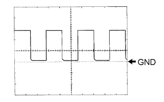
Inspect using an oscilloscope.
-
Waveform 1 (Reference)
Item Content Symbols (Terminal No.) TACO (A33-33) - GND (A33-29) Tool Setting 5 V/DIV., 20 msec./DIV. Condition Engine idling Tech Tips
As engine speed increases, the wavelength shortens.
-
-
-
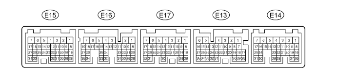
CHECK ECM (for 1GR-FE)
-
Measure the voltage of the connectors.
Tech Tips
Symbols (Terminal No.) Wiring Color Terminal Description Condition Specified Condition ACT (E13-25) - E01 (E15-7) R-L - W-B Magnet on permit signal Ignition switch START
A/C switch OFF
Blower switch OFF
Below 1 V ACT (E13-25) - E01 (E15-7) R-L - W-B Magnet on permit signal Ignition switch START
A/C switch ON
Blower switch ON
10 to 14 V AC1 (E13-24) - E01 (E15-7) Y - W-B Idle-up request signal Ignition switch START
A/C magnet clutch is engaged
Below 1 V AC1 (E13-24) - E01 (E15-7) Y - W-B Magnet on permit signal Ignition switch START
A/C magnet clutch is not engaged
10 to 14 V If the result is not as specified, the ECM may have a malfunction.
-
-
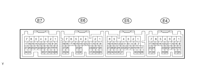
CHECK ECM (for 2TR-FE)
-
Measure the voltage of the connectors.
Symbols (Terminal No.) Wiring Color Terminal Description Condition Specified Condition ACT (E9-25) - E01 (E11-6) R-L - W-B Magnet on permit signal Ignition switch START
A/C switch OFF
Blower switch OFF
Below 1 V ACT (E9-25) - E01 (E11-6) R-L - W-B Magnet on permit signal Ignition switch START
A/C switch ON
Blower switch ON
10 to 14 V AC1 (E9-24) - E01 (E11-6) Y - W-B Idle-up request signal Ignition switch START
A/C magnet clutch is engaged
Below 1 V AC1 (E9-24) - E01 (E11-6) Y - W-B Magnet on permit signal Ignition switch START
A/C magnet clutch is not engaged
10 to 14 V If the result is not as specified, the ECM may have a malfunction.
-
-
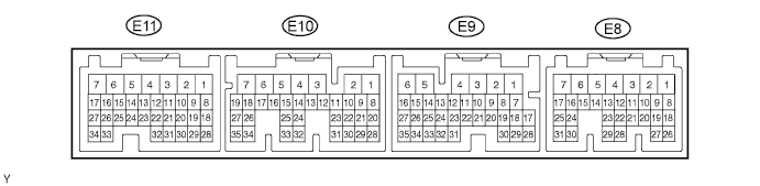
CHECK ECM (for 1KD-FTV)
-
Measure the voltage of the connectors.
Symbols (Terminal No.) Wiring Color Terminal Description Condition Specified Condition ACT (E5-19) - E01 (E7-7) R-L - W-B Magnet on permit signal Ignition switch START
A/C switch OFF
Blower switch OFF
Below 1 V ACT (E5-19) - E01 (E7-7) R-L - W-B Magnet on permit signal Ignition switch START
A/C switch ON
Blower switch ON
10 to 14 V AC1 (E5-18) - E01 (E7-7) Y - W-B Idle-up request signal Ignition switch START
A/C magnet clutch is engaged
Below 1 V AC1 (E5-18) - E01 (E7-7) Y - W-B Magnet on permit signal Ignition switch START
A/C magnet clutch is not engaged
10 to 14 V THWO (E4-2) - E01 (E7-7)* P - W-B Water temperature signal Ignition switch START Pulse generation HSW (E4-20) - E01 (E7-7)* L-W - W-B Heater switch output signal for idle-up Ignition switch START
Heater switch ON
Blower switch ON
Temperature control knob: Max HOT
Engine coolant temperature 65°C (149 °F)
Below 1 V HSW (E4-20) - E01(E7-7)* L-W - W-B Heater switch output signal for idle-up Ignition switch START
Heater switch OFF
Blower switch ON
Temperature control knob: except Max HOT
Engine coolant temperature 65°C (149 °F)
10 to 14 V TACH (E4-4) - E01 (E7-7)* B-W - W-B Tachometer signal Engine running Pulse generation
(see waveform 1)
If the result is not as specified, the ECM may have a malfunction.
Tech Tips
*: w/ PTC Heater
-
Inspect using an oscilloscope (w/PTC heater only)
-
Waveform 1 (Reference)
Item Content Symbols (Terminal No.) TACH (E4-4) - E01 (E7-7) Tool Setting 5 V/DIV., 20 msec./DIV. Condition Engine idling Tech Tips
As engine speed increases, the wavelength shortens.
-
-