AIR CONDITIONING SYSTEM (for Automatic Air Conditioning System), Diagnostic DTC:13

| DTC Code | DTC Name |
|---|---|
| 13 | Evaporator Temperature Sensor Circuit |
DESCRIPTION
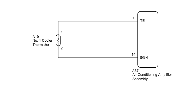
The No. 1 cooler thermistor is installed on the evaporator in the air conditioning unit. It detects the temperature of the cooled air that has passed through the evaporator which is then used in air conditioning control. The resistance of the No. 1 cooler thermistor changes in accordance with the temperature of the cooled air that has passed through the evaporator. As the temperature decreases, the resistance increases. As the temperature increases, the resistance decreases.
The air conditioning amplifier assembly applies voltage (5 V) to the No. 1 cooler thermistor and reads voltage changes as the resistance of the No. 1 cooler thermistor changes. This thermistor is used for frost prevention.
| DTC Code | DTC Detection Condition | Trouble Area |
|---|---|---|
| 13 | An open or short in evaporator temperature sensor circuit |
|
WIRING DIAGRAM
INSPECTION PROCEDURE
PROCEDURE
-
CHECK AIR CONDITIONING AMPLIFIER ASSEMBLY
-
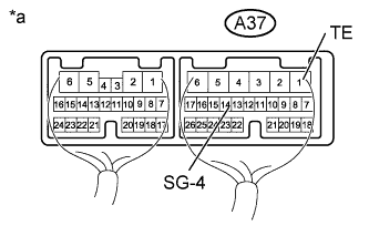
Text in Illustration *a Component with harness connected
(Air Conditioning Amplifier Assembly)
Remove the air conditioning amplifier assembly with its connectors still connected Click here.
-
Measure the voltage according to the value(s) in the table below.
Standard Voltage Tester Connection Condition Specified Condition A37-1 (TE) - A37-14 (SG-4)
-
Ignition switch ON
-
Evaporator temperature 0°C (32°F)
2.0 to 2.4 V
-
Ignition switch ON
-
Evaporator temperature 15°C (59°F)
1.4 to 1.8 V Tech Tips
As the temperature increases, the voltage decreases.
Result Result Proceed to OK (When troubleshooting according to problem symptoms table.) A OK (When troubleshooting according to DTC.) B NG C -
B 
REPLACE AIR CONDITIONING AMPLIFIER ASSEMBLY Click here
C 
INSPECT NO. 1 COOLER THERMISTOR Click here
A 
PROCEED TO NEXT SUSPECTED AREA SHOWN IN PROBLEM SYMPTOMS TABLE Click here
-
-
INSPECT NO. 1 COOLER THERMISTOR
-
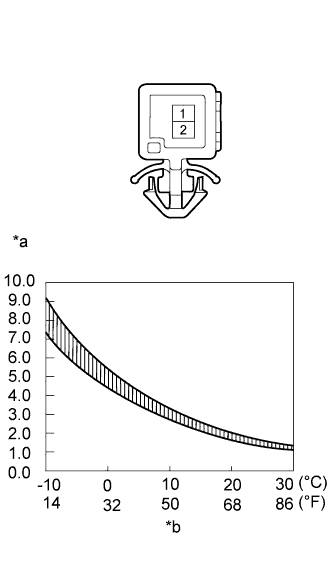
Text in Illustration *a Resistance (kΩ) *b Temperature Remove the No. 1 cooler thermistor Click here.
-
Measure the resistance according to the value(s) in the table below.
Standard Resistance Tester Connection Condition Specified Condition 1 - 2 -10°C (14°F) 7.30 to 9.10 kΩ -5°C (23°F) 5.65 to 6.95 kΩ 0°C (32°F) 4.40 to 5.35 kΩ 5°C (41°F) 3.40 to 4.15 kΩ 10°C (50°F) 2.70 to 3.25 kΩ 15°C (59°F) 2.14 to 2.58 kΩ 20°C (68°F) 1.71 to 2.05 kΩ 25°C (77°F) 1.38 to 1.64 kΩ 30°C (86°F) 1.11 to 1.32 kΩ Note
-
Even slightly touching the No. 1 cooler thermistor may change the resistance value. Be sure to hold the connector of the No. 1 cooler thermistor.
-
When measuring the resistance, the No. 1 cooler thermistor temperature must be the same as the ambient temperature.
Tech Tips
As the temperature increases, the resistance decreases (Refer to the graph).
-
NG
REPLACE NO. 1 COOLER THERMISTOR Click here
OK 
-
-
CHECK HARNESS AND CONNECTOR (NO. 1 COOLER THERMISTOR - AIR CONDITIONING AMPLIFIER)
-
Disconnect the A19 No. 1 cooler thermistor connector.
-
Disconnect the A37 air conditioning amplifier assembly connector.
-
Measure the resistance according to the value(s) in the table below.
Standard Resistance Tester Connection Condition Specified Condition A37-1 (TE) - A19-1 Always Below 1 Ω A37-14 (SG-4) - A19-2 A37-1 (TE) - Body ground Always 10 kΩ or higher A37-14 (SG-4) - Body ground
NG
REPAIR OR REPLACE HARNESS OR CONNECTOR
OK
REPLACE AIR CONDITIONING AMPLIFIER ASSEMBLY Click here
-