STEERING COLUMN ASSEMBLY INSTALLATION

-
INSTALL STEERING COLUMN ASSEMBLY
-
Install the steering column with the 3 bolts.
- Torque:
- 21 N*m { 214 kgf*cm, 15 ft.*lbf }
-
-
INSTALL STEERING COLUMN HOLE COVER SUB-ASSEMBLY
-
Install the cover with the 3 bolts.
- Torque:
- 5.0 N*m { 51 kgf*cm, 44 in.*lbf }
-
-
CONNECT CONNECTOR
-
Connect the connectors and attach the wire harness clamps to the steering column.
-
-
INSTALL STEERING SLIDING YOKE
-
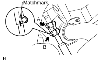
Align the matchmarks on the steering yoke and steering intermediate shaft.
-
Install the bolt labeled B.
- Torque:
- 35 N*m { 355 kgf*cm, 26 ft.*lbf }
-
Tighten the bolt labeled A.
- Torque:
- 35 N*m { 355 kgf*cm, 26 ft.*lbf }
-
-
INSTALL LOWER INSTRUMENT PANEL SUB-ASSEMBLY
-
Attach the 2 guides to install the lower instrument panel.
-
Connect the connectors and attach the clamps.
-
Connect the hood lock control cable, fuel lid lock control cable and DLC3.
-
Install the 2 bolts <C>, nut <D> and 3 screws <E>.
-
Install the 2 clips <B>.
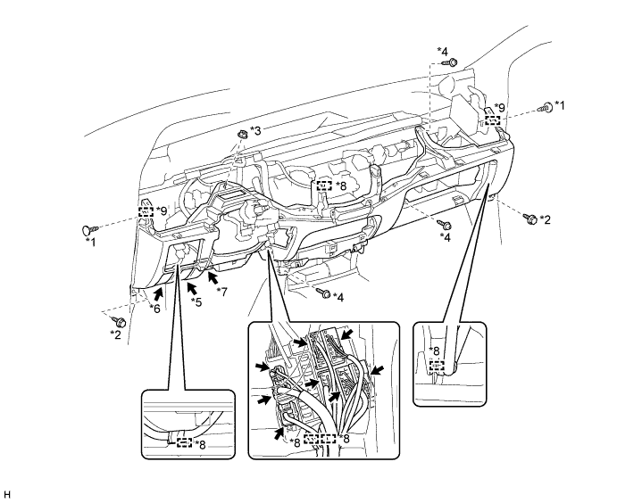
Text in Illustration *1 Clip <B> *2 Bolt <C> *3 Nut <D> *4 Screw <E> *5 Hood Lock Control Cable *6 Fuel Lid Lock Control Cable *7 DLC3 *8 Clamp *9 Guide - -
-
-
INSTALL UPPER INSTRUMENT PANEL SUB-ASSEMBLY
-
Attach the 5 guides and 8 claws to install the upper instrument panel.
-
Install the 2 bolts <A> and 2 screws <B>.
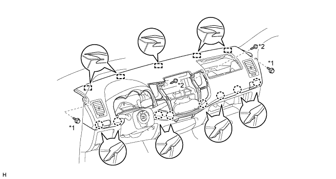
Text in Illustration *1 Bolt <A> *2 Screw <B>
-
-
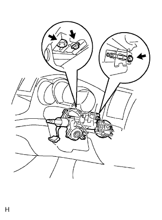
INSTALL HEADLIGHT DIMMER SWITCH ASSEMBLY
-
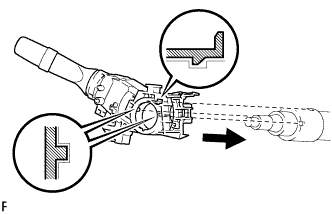
Install the headlight dimmer switch assembly to the steering column, making sure that the stopper protrusions and cutout parts align.
-
Using needle-nose pliers, install the band clamp as shown in the illustration.
-
Connect the connector.
-
-
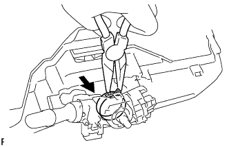
INSTALL WIPER AND WASHER SWITCH ASSEMBLY
-
Attach the claw to install the windshield wiper switch.
Note
Do not push the claw with excessive force as damage may occur.
-
Connect the connectors.
-
-
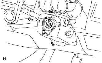
INSTALL SPIRAL CABLE SUB-ASSEMBLY
-
Check that the front wheels are facing straight ahead.
-
Set the turn signal switch to the neutral position.
Note
Make sure that the turn signal switch is in the neutral position, as the pin of the turn signal switch may be snapped.
-
Install the spiral cable.
Note
When replacing the spiral cable with a new one, remove the lock pin before installing the steering wheel.
-
Connect the connectors to the spiral cable.
Note
When handling the airbag connector, do not damage the airbag wire harness.
-
-
INSTALL INSTRUMENT CLUSTER FINISH PANEL NO.1
-
Attach the 2 claws and 3 guides to install the No. 1 instrument cluster finish panel.
-
Install the clip <C>.
-
-
INSTALL STEERING COLUMN UPPER COVER
-
INSTALL STEERING COLUMN LOWER COVER
-
Install the lower cover with the 3 screws.
- Torque:
- 2.0 N*m { 20 kgf*cm, 18 in.*lbf }
-
-
ADJUST SPIRAL CABLE
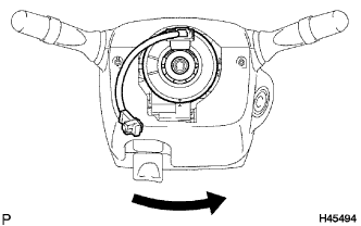
-
Slowly rotate the spiral cable counterclockwise by hand until it feels firm.
Note
Do not use the airbag wire harness to turn the spiral cable.
-
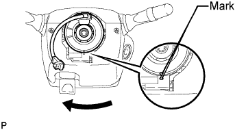
Rotate the spiral cable clockwise approximately 2.5 turns to align the marks.
Note
Do not use the airbag wire harness to turn the spiral cable.
Tech Tips
The spiral cable will rotate approximately 2.5 turns to the left and right from the center.
-
-
INSTALL STEERING WHEEL ASSEMBLY
-
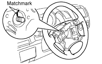
Align the matchmarks on the steering wheel and main shaft.
-
Install the steering set nut.
- Torque:
- 50 N*m { 510 kgf*cm, 37 ft.*lbf }
-
-
INSTALL NO. 2 STEERING WHEEL ORNAMENT
-
Attach the 2 pins to install the steering wheel ornament.
-
Install the screw.
-
-
INSTALL NO. 1 STEERING WHEEL ORNAMENT
-
Attach the 2 pins to install the steering wheel ornament.
-
Install the screw.
-
-
INSTALL STEERING PAD SWITCH LH (w/o Multi-information Display)
Tech Tips
Refer to the step "INSTALL STEERING PAD SWITCH ASSEMBLY".
-
INSTALL STEERING PAD SWITCH ASSEMBLY (w/ Multi-information Display)
-
Attach the 4 pins to install the steering pad switch.
-
Install the 2 screws.
-
Connect the connectors and attach the 2 clamps.
-
-
INSTALL STEERING PAD ASSEMBLY
-
PLACE FRONT WHEELS FACING STRAIGHT AHEAD
-
CONNECT CABLE TO NEGATIVE BATTERY TERMINAL
-
PERFORM INITIALIZATION
-
Perform initialization Click here.
Note
Certain systems need to be initialized after disconnecting and reconnecting the cable from the negative (-) battery terminal.
-