STEERING COLUMN ASSEMBLY REASSEMBLY

-
INSTALL STEERING MAIN SHAFT ASSEMBLY
-
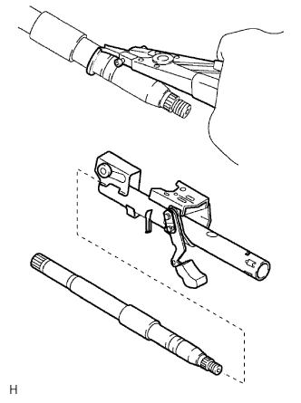
Using a snap ring expander, install a new steering main shaft snap ring (inner side) to the steering main shaft.
-
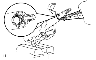
Install the steering main shaft to the steering column tube.
-
Using a snap ring expander, install a steering main shaft snap ring.
-
-
INSTALL STEERING MAIN SHAFT BEARING
-
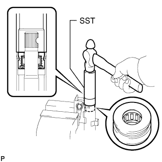
Using SST and a hammer, tap in the bearing until it is flush with the edge of the steering column tube.
- SST
- 09608-06041
-
-
INSTALL KEY INTER LOCK SOLENOID
-
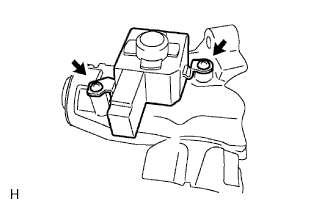
Install the solenoid to the steering column bracket upper with the 2 screws.
-
-
INSTALL IGNITION SWITCH ASSEMBLY
-
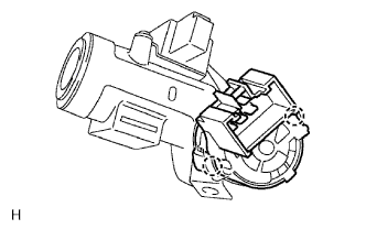
Install the switch to the steering column bracket upper with the 2 claws.
-
-
INSTALL UNLOCK WARNING SWITCH ASSEMBLY
-
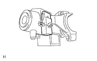
Install the switch to the steering column bracket upper with the 2 claws.
-
-
INSTALL IGNITION SWITCH LOCK CYLINDER ASSEMBLY
-
Make sure that the lock cylinder is on ACC.
-
Install the ignition switch lock cylinder.
-
-
INSTALL STEERING LOCK OPERATION
-
Check that the steering lock mechanism is activated when the key is removed.
-
Check that the steering lock mechanism is deactivated when the key is inserted and turned to the ACC position.
If there is any abnormality, replace the ignition switch lock cylinder assembly.
-
-
INSTALL STEERING COLUMN UPPER WITH SWITCH BRACKET ASSEMBLY
-
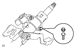
Install the steering column upper bracket and steering column upper clamp with 2 new tapered-head bolts.
-
Tighten the 2 tapered-head bolts until the bolt heads break off.
-
-
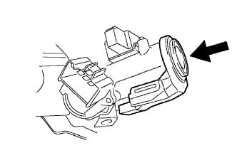
INSTALL KEY CYLINDER LIGHT ASSEMBLY (w/o Engine Immobiliser System)
-
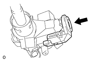
Connect the connector.
-
Push in the key cylinder light assembly in the direction indicated by the arrow in the illustration to install it.
-
-
INSTALL TRANSPONDER KEY AMPLIFIER (w/ Engine Immobiliser System)
-
Align the amplifier with the installation position of the upper bracket.
-
Push up the amplifier and connect it to the upper bracket.
Note
Do not apply excessive force to the amplifier as it may be damaged.
-
-
INSTALL NO. 2 STEERING INTERMEDIATE SHAFT SUB-ASSEMBLY
-
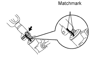
Align the matchmarks on the steering intermediate shaft and steering gear.
-
Install the steering intermediate shaft to the steering gear with the bolt.
- Torque:
- 35 N*m { 35 kgf*cm, 26 ft.*lbf }
-
-
INSTALL STEERING SLIDING WITH COUPLING YOKE SUB-ASSEMBLY
-
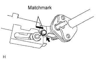
Align the matchmarks on the yoke and steering main shaft.
-
Install the steering yoke with the bolt.
- Torque:
- 28 N*m { 286 kgf*cm, 21 ft.*lbf }
-