STEERING COLUMN ASSEMBLY REMOVAL

-
PRECAUTION
-
DISCONNECT CABLE FROM NEGATIVE BATTERY TERMINAL
CAUTION:
Wait at least 90 seconds after disconnecting the cable from the negative (-) battery terminal to prevent airbag and seat belt pretensioner activation.
-
PLACE FRONT WHEELS FACING STRAIGHT AHEAD
-
REMOVE STEERING PAD ASSEMBLY
-
REMOVE NO. 2 STEERING WHEEL ORNAMENT
-
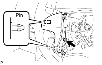
Remove the screw.
-
Detach the 2 pins and remove the steering wheel ornament.
-
-
REMOVE NO. 1 STEERING WHEEL ORNAMENT
-
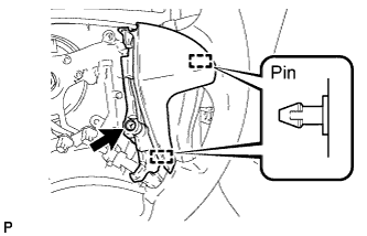
Remove the screw.
-
Detach the 2 pins and remove the steering wheel ornament.
-
-
REMOVE STEERING PAD SWITCH LH (w/o Multi-information Display)
Tech Tips
Refer to the step "REMOVE STEERING PAD SWITCH ASSEMBLY".
-
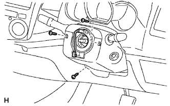
REMOVE STEERING PAD SWITCH ASSEMBLY (w/ Multi-information Display)
-
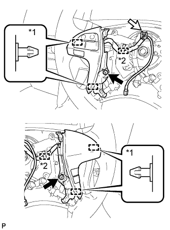
Text in Illustration *1 Pin *2 Clamp Disconnect the connectors and detach the 2 clamps.
-
Remove the 2 screws.
-
Detach the 4 pins and remove the steering pad switch.
-
-
REMOVE STEERING WHEEL ASSEMBLY
-
Remove the steering wheel set nut.
-
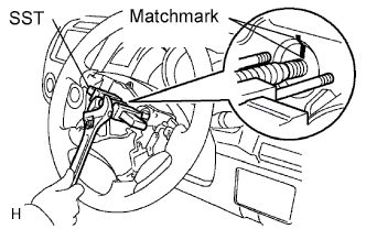
Place matchmarks on the steering wheel and main shaft.
-
Using SST, remove the steering wheel.
- SST
- 09950-50013 ( 09951-05010, 09952-05010, 09953-05020, 09954-05021 )
-
-
REMOVE STEERING COLUMN LOWER COVER
-
Remove the 3 screws and lower cover.
-
-
REMOVE STEERING COLUMN UPPER COVER
-
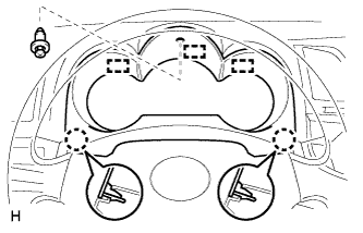
REMOVE INSTRUMENT CLUSTER FINISH PANEL NO.1
-
Remove the clip <C>.
-
Detach the 2 claws and 3 guides and remove the No. 1 instrument cluster finish panel.
-
-
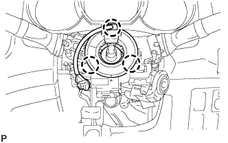
REMOVE SPIRAL CABLE SUB-ASSEMBLY
-
Disconnect the connectors from the spiral cable.
Note
When handling the airbag connector, do not damage the airbag wire harness.
-
Detach the 3 claws and remove the spiral cable.
-
-
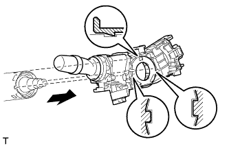
REMOVE WIPER AND WASHER SWITCH ASSEMBLY
-
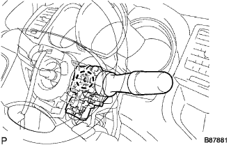
Disconnect the connectors.
-
Detach the claw and remove the windshield wiper switch.
Note
Do not push the claw with excessive force as damage may occur.
-
-
REMOVE HEADLIGHT DIMMER SWITCH ASSEMBLY
-
Disconnect the connector.
-
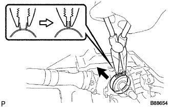
Using needle-nose pliers, remove the band clamp as shown in the illustration.
-
While loosening the band clamp as shown in the illustration, detach the claw to remove the headlight dimmer switch assembly.
Note
If the claw is pressed forcefully, it will break.
-
-
REMOVE UPPER INSTRUMENT PANEL SUB-ASSEMBLY
-
REMOVE LOWER INSTRUMENT PANEL SUB-ASSEMBLY
-
Using a clip remover, remove the 2 clips <B>.
-
Remove the 2 bolts <C>, nut <D> and 3 screws <E>.
-
Disconnect the hood lock control cable, fuel lid lock control cable and DLC3.
-
Disconnect the connectors and detach the clamps.
-
Detach the 2 guides and remove the lower instrument panel.
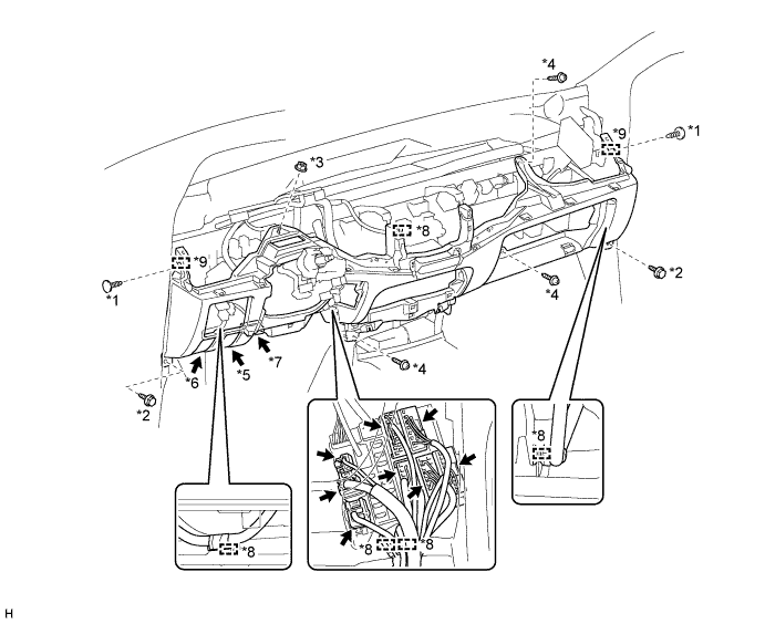
Text in Illustration *1 Clip <B> *2 Bolt <C> *3 Nut <D> *4 Screw <E> *5 Hood Lock Control Cable *6 Fuel Lid Lock Control Cable *7 DLC3 *8 Clamp *9 Guide - -
-
-
DISCONNECT STEERING SLIDING YOKE
-
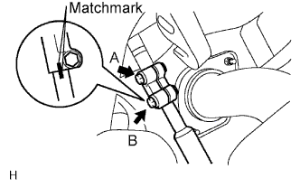
Loosen the bolt labeled A.
-
Place matchmarks on the steering yoke and steering intermediate shaft.
-
Remove the bolt labeled B.
-
-
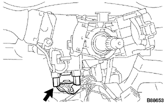
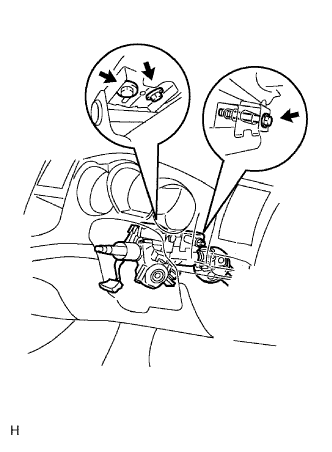
DISCONNECT CONNECTOR
-
Disconnect the connectors and wire harness clamps from the steering column.
-
-
REMOVE STEERING COLUMN HOLE COVER SUB-ASSEMBLY
-
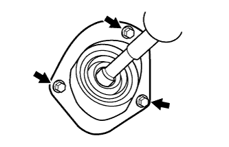
Remove the 3 bolts and cover.
-
-
REMOVE STEERING COLUMN ASSEMBLY
-
Remove the 3 bolts and pull out the steering column together with the steering sliding w/ coupling yoke.
-