PARKING BRAKE CABLE INSTALLATION

-
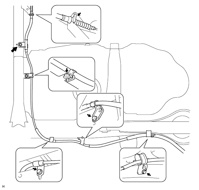
INSTALL NO. 3 PARKING BRAKE CABLE ASSEMBLY
-
Install the cable with the 4 bolts and nut as shown in the illustration.
- Torque:
- 25.5 N*m { 260 kgf*cm, 19 ft.*lbf }
-
Install the No. 3 clip as shown in the illustration.
-
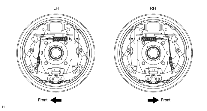
Connect the cable to the parking brake shoe lever LH and backing plate LH.
-
Connect the cable to the backing plate with the 2 bolts.
- Torque:
- 9.0 N*m { 92 kgf*cm, 80 in.*lbf }
-
Connect the cable to the lever Click here.
-
-
-
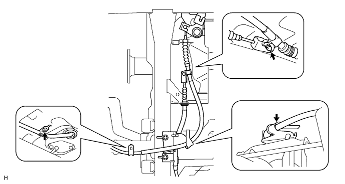
INSTALL NO. 2 PARKING BRAKE CABLE ASSEMBLY
-
Install the cable with the 4 bolts as shown in the illustration.
- Torque:
- 25.5 N*m { 260 kgf*cm, 19 ft.*lbf }
-
Connect the cable to the parking brake shoe lever RH and backing plate RH.
-
Connect the cable to the backing plate with the 2 bolts.
- Torque:
- 9.0 N*m { 92 kgf*cm, 80 in.*lbf }
-
Connect the cable to the lever Click here.
-
-
Connect the cable to the equalizer as shown in the illustration.
-
Install the No. 2 heat insulator with the 3 bolts.
- Torque:
- 25.5 N*m { 260 kgf*cm, 19 ft.*lbf }
-
-
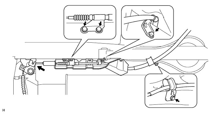
INSTALL NO. 1 PARKING BRAKE CABLE ASSEMBLY
-
Connect the cable to the parking brake lever Click here.
-
Install the cable with the bolt.
- Torque:
- 5.0 N*m { 51 kgf*cm, 44 in.*lbf }
-
Connect the cable to the equalizer.
-
Connect the cable to the No. 3 cable.
-
Install the pin and No. 1 clip.
-
Attach the cable to the cable support bracket.
-
Install the No. 1 heat insulator with the 2 bolts.
- Torque:
- 6.0 N*m { 61 kgf*cm, 53 in.*lbf }
-
-
CHECK REAR BRAKE DRUM INSTALLATION
-
Check that each part is installed properly.
-
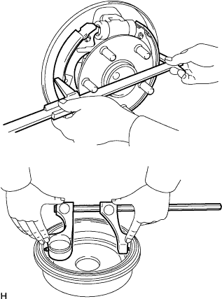
Measure the inside diameter of the drum and the diameter of the shoes. Check that the difference between the diameters is the correct shoe clearance.
Standard shoe clearance 0.6 mm (0.0236 in.) Note
There should be no oil or grease on the contact surfaces of the shoe lining and drum.
-
-
INSTALL REAR BRAKE DRUM SUB-ASSEMBLY AND NEW GASKET
-
ADJUST BRAKE SHOE CLEARANCE
-
INSTALL REAR WHEEL
- Torque:
- 105 N*m { 1,071 kgf*cm, 77 ft.*lbf }
-
CHECK PARKING BRAKE LEVER TRAVEL
-
Pull the lever upward with a force of approximately 200 N (20 kgf, 45 lbf) and count the number of clicks.
OK 7 to 9 clicks (without rear brake dragging)
-
-
ADJUST PARKING BRAKE LEVER TRAVEL
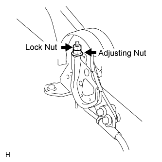
-
Turn the No. 1 wire adjusting nut until the lever travel is correct.
OK 7 to 9 clicks (without rear brake dragging) <Lever pulling force: approximately 200 N (20 kgf, 45 lbf)> -
Tighten the lock nut.
- Torque:
- 5.2 N*m { 53 kgf*cm, 46 in.*lbf }
Tech Tips
If the lever travel cannot be fully adjusted with this procedure, proceed to the "ADJUST PARKING BRAKE TURN BUCKLE" procedure.
-
-
ADJUST PARKING BRAKE TURN BUCKLE
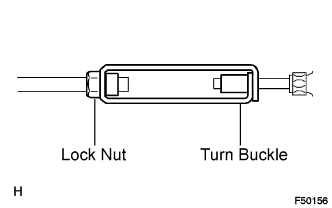
-
Loosen the lock nut and turn buckle until the lever travel is correct.
-
Tighten the lock nut.
- Torque:
- 5.0 N*m { 51 kgf*cm, 44 in.*lbf }
-
-
INSTALL CONSOLE BOX ASSEMBLY
-
CONNECT CABLE TO NEGATIVE BATTERY TERMINAL
-
PERFORM INITIALIZATION
-
Perform initialization Click here.
Note
Certain systems need to be initialized after disconnecting and reconnecting the cable from the negative (-) battery terminal.
-