PARKING BRAKE CABLE REMOVAL

-
DISCONNECT CABLE FROM NEGATIVE BATTERY TERMINAL
CAUTION:
Wait at least 90 seconds after disconnecting the cable from the negative (-) battery terminal to prevent airbag and seat belt pretensioner activation.
-
REMOVE REAR WHEEL
-
REMOVE REAR BRAKE DRUM SUB-ASSEMBLY
-
Release the parking brake lever, and remove the drum and gasket.
Tech Tips
If the drum cannot be removed easily, perform the following procedures.
-
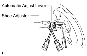
Remove the hole plug (adjust) and insert a screwdriver into the hole on the backing plate, and hold the automatic adjust lever away from the adjuster.
-
Using another screwdriver, compress the shoe adjuster by turning the adjusting wheel.
-
-
REMOVE CONSOLE BOX ASSEMBLY
-
REMOVE NO. 1 PARKING BRAKE CABLE ASSEMBLY
-
Disconnect the cable from the parking brake lever Click here.
-
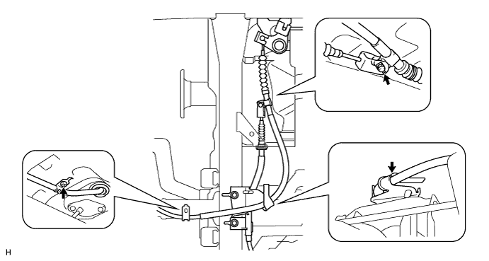
Remove the 2 bolts and No. 1 heat insulator.
-
Remove the No. 1 clip and pin.
-
Disconnect the cable from the No. 3 cable.
-
Disconnect the cable from the equalizer.
-
Remove the bolt holding the cable.
-
Detach the cable from the cable support bracket.
-
-
REMOVE NO. 2 PARKING BRAKE CABLE ASSEMBLY
-
Disconnect the cable from the parking brake shoe lever RH and backing plate RH.
-
Disconnect the cable from the lever Click here.
-
Remove the 2 bolts and disconnect the cable from the backing plate.
-
-
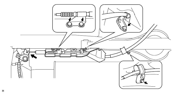
Remove the 3 bolts and No. 2 heat insulator.
-
Disconnect the cable from the equalizer as shown in the illustration.
-
Remove the 4 bolts and cable as shown in the illustration.
-
-
REMOVE NO. 3 PARKING BRAKE CABLE ASSEMBLY
-
Disconnect the cable from the parking brake shoe lever LH and backing plate LH.
-
Disconnect the cable from the lever Click here.
-
Remove the 2 bolts and disconnect the cable from the backing plate.
-
-
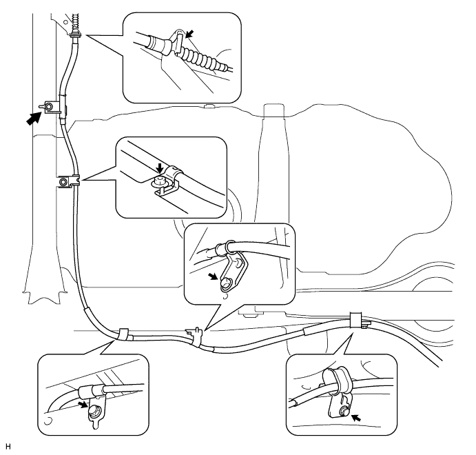
Remove the No. 3 clip as shown in the illustration.
-
Remove the 4 bolts, nut and cable as shown in the illustration.
-