PARKING BRAKE LEVER INSTALLATION

-
INSTALL PARKING BRAKE LEVER SUB-ASSEMBLY
-
Install the switch to the lever with the screw.
-
Connect the switch connector.
-
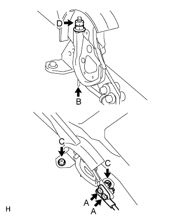
Connect the cable to the lever with the 2 bolts and 2 nuts (labeled A).
- Torque:
- 14.5 N*m { 148 kgf*cm, 11 ft.*lbf }
-
Return the claw (labeled B) to its original position.
-
Install the lever with the 2 bolts (labeled C).
- Torque:
- 12.5 N*m { 127 kgf*cm, 9 ft.*lbf }
-
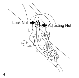
Install the wire adjusting nut and lock nut (labeled D).
- Torque:
- 5.2 N*m { 53 kgf*cm, 46 in.*lbf }
-
-
CHECK PARKING BRAKE LEVER TRAVEL
-
Pull the lever upward with a force of approximately 200 N (20 kgf, 45 lbf) and count the number of clicks.
OK 7 to 9 clicks (without rear brake dragging)
-
-
ADJUST PARKING BRAKE LEVER TRAVEL
-
Turn the No. 1 wire adjusting nut until the lever travel is correct.
OK 7 to 9 clicks (without rear brake dragging) <Lever pulling force: approximately 200 N (20 kgf, 45 lbf)> -
Tighten the lock nut.
- Torque:
- 5.2 N*m { 53 kgf*cm, 46 in.*lbf }
Tech Tips
If the lever travel cannot be fully adjusted with this procedure, proceed to the "ADJUST PARKING BRAKE TURN BUCKLE" procedure.
-
-
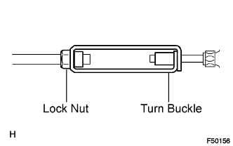
ADJUST PARKING BRAKE TURN BUCKLE
-
Loosen the lock nut and turn buckle until the lever travel is correct.
-
Tighten the lock nut.
- Torque:
- 5.0 N*m { 51 kgf*cm, 44 in.*lbf }
-
-
INSTALL CONSOLE BOX ASSEMBLY
-
CONNECT CABLE TO NEGATIVE BATTERY TERMINAL
-
PERFORM INITIALIZATION
-
Perform initialization Click here.
Note
Certain systems need to be initialized after disconnecting and reconnecting the cable from the negative (-) battery terminal.
-