PARKING BRAKE SYSTEM ADJUSTMENT

-
CHECK PARKING BRAKE LEVER TRAVEL
-
Pull the lever upward with a force of approximately 200 N (20 kgf, 45 lbf) and count the number of clicks.
OK 7 to 9 clicks (without rear brake dragging)
-
-
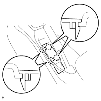
REMOVE PARKING BRAKE HOLE COVER SUB-ASSEMBLY
-
Detach the 4 claws and remove the parking brake hole cover.
-
-
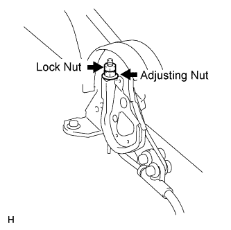
LOOSEN LOCK NUT AND NO. 1 WIRE ADJUSTING NUT
-
REMOVE REAR WHEEL
-
ADJUST BRAKE SHOE CLEARANCE
-
INSTALL REAR WHEEL
- Torque:
- 105 N*m { 1071 kgf*cm, 77 ft.*lbf }
-
ADJUST PARKING BRAKE LEVER TRAVEL
-
Turn the No. 1 wire adjusting nut until the lever travel is correct.
OK 7 to 9 clicks (without rear brake dragging) <Lever pulling force: approximately 200 N (20 kgf, 45 lbf)> -
Tighten the lock nut.
- Torque:
- 5.2 N*m { 53 kgf*cm, 46 in.*lbf }
Tech Tips
If the lever travel cannot be fully adjusted with this procedure, proceed to the "ADJUST PARKING BRAKE TURN BUCKLE" procedure.
-
-
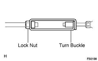
ADJUST PARKING BRAKE TURN BUCKLE
-
Loosen the lock nut and turn buckle until the lever travel is correct.
-
Tighten the lock nut.
- Torque:
- 5.0 N*m { 51 kgf*cm, 44 in.*lbf }
-
-
INSTALL PARKING BRAKE HOLE COVER SUB-ASSEMBLY
-
Attach the 4 claws to install the parking brake hole cover.
-