REAR BRAKE REASSEMBLY

Tech Tips
-
Use the same procedures for the LH side and RH side.
-
The procedures listed below are for the LH side.
-
INSTALL REAR WHEEL BRAKE CYLINDER CUP
-
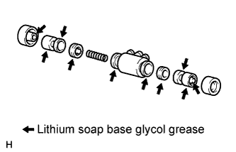
Apply lithium soap base glycol grease to 2 new cups and 2 pistons.
-
Install the 2 cups to the 2 pistons.
-
Install the compression spring and 2 pistons to the cylinder.
-
Install 2 new cylinder dust boots to the cylinder.
-
-
TEMPORARILY TIGHTEN REAR BRAKE DRUM BLEEDER PLUG
-
Install the bleeder plug to the cylinder.
Tech Tips
The bleeder plug will be tightened to a torque specification in the "BLEED AIR FROM BRAKE LINE" procedures.
-
Install the cap.
-
-
INSTALL REAR WHEEL BRAKE CYLINDER ASSEMBLY LH
-
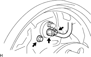
Install the cylinder with the 2 bolts.
- Torque:
- 12 N*m { 117 kgf*cm, 8 ft.*lbf }
-
Using a union nut wrench, connect the brake line.
- Torque:
- 15 N*m { 155 kgf*cm, 11 ft.*lbf }
Note
Use the formula to calculate special torque values for situations where a union nut wrench is combined with a torque wrench Click here.
-
-
APPLY HIGH TEMPERATURE GREASE
-
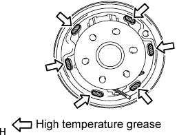
Apply high temperature grease to the surface of the backing plate where the shoe will be attached.
-
Apply high temperature grease to the anchor block plate and cable setting area.
-
-
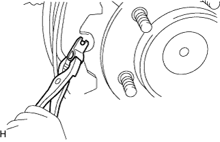
INSTALL REAR BRAKE PARKING BRAKE SHOE LEVER SUB-ASSEMBLY
-
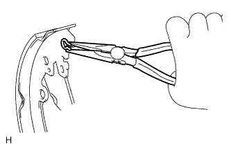
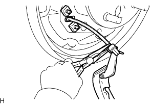
Using needle-nose pliers, install the lever with a new C-washer.
-
-
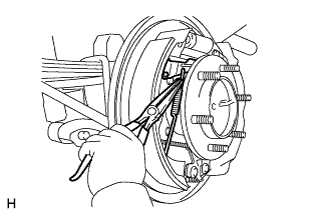
INSTALL BRAKE SHOES
-
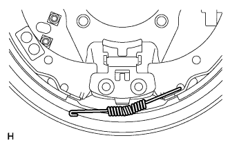
Using needle-nose pliers, connect the No. 3 parking brake cable to the parking brake shoe lever.
-
Install the strut set and return spring to the shoe.
-
Attach the support clip to the exposed threads of the strut set.
Note
The support clip should not contact the adjuster nut.
-
Using needle-nose pliers, hook the support clip around the spring.
Note
Be careful not to damage the spring.
-
Install the front and rear brake shoes.
-
Move one of the shoes upward and install the shoe tension spring.
-
Install the shoe front or rear side to the cylinder. Then install the other side of the shoe to the other side of the cylinder.
Tech Tips
After one side of the shoe is installed to the cylinder, hold that side of the shoe steady. Then widen the opening of the shoe by pulling the other side of the shoe outward and install it to the other side of the cylinder.
Note
Be careful not to damage the cylinder dust boot.
-
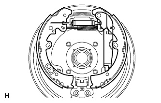
Using pliers, install the front brake shoe, rear brake shoe, pins and shoe hold down springs.
-
-
INSTALL REAR BRAKE AUTOMATIC ADJUST LEVER LH
-
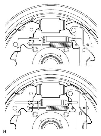
Using needle-nose pliers, install the lever and lever tension spring.
-
-
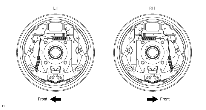
CHECK REAR BRAKE DRUM INSTALLATION
-
Check that each part is installed properly.
-
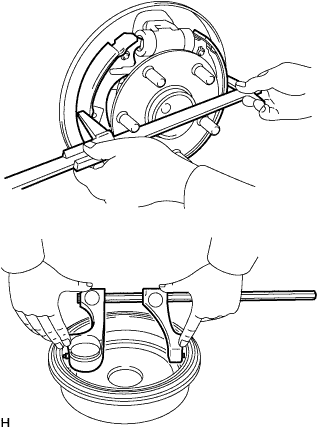
Measure the inside diameter of the drum and the diameter of the shoes. Check that the difference between the diameters is the correct shoe clearance.
Standard shoe clearance 0.6 mm (0.0236 in.) Note
There should be no oil or grease on the contact surfaces of the shoe lining and drum.
-
-
INSTALL REAR BRAKE DRUM AND NEW GASKET
-
FILL RESERVOIR WITH BRAKE FLUID
Fluid SAE J1703 or FMVSS No. 116 DOT3 -
BLEED AIR FROM BRAKE MASTER CYLINDER
Tech Tips
If the master cylinder has been disassembled or if the reservoir becomes empty, bleed air from the master cylinder.
-
Using a union nut wrench, disconnect the 2 brake lines from the master cylinder.
-
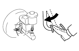
Slowly depress and hold the brake pedal.
-
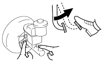
Cover the outer holes with your fingers, and release the pedal.
-
Repeat the 2 previous steps 3 or 4 times.
-
Using a union nut wrench, connect the 2 brake lines to the master cylinder.
- Torque:
- 15 N*m { 155 kgf*cm, 11 ft.*lbf }
Note
Use the formula to calculate special torque values for situations where a union nut wrench is combined with a torque wrench Click here.
-
-
BLEED AIR FROM BRAKE LINE
-
Remove the bleeder plug cap.
-
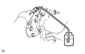
Connect the vinyl tube to the bleeder plugs.
-
Depress the brake pedal several times, and then loosen the bleeder plug with the pedal depressed.
-
When fluid stops coming out, immediately tighten the bleeder plug. Then release the pedal.
-
Repeat the 2 previous steps until all the air in the brake fluid is gone.
-
Tighten the bleeder plug.
- Torque:
- 11 N*m { 110 kgf*cm, 8 ft.*lbf, for front brake }
- 10 N*m { 102 kgf*cm, 7 ft.*lbf, for rear brake }
-
Install the cap.
-
Bleed air from the brake line for each wheel by repeating the above procedures.
-
-
BLEED AIR FROM CLUTCH LINE (for Manual Transmission)
-
Remove the brake master cylinder reservoir filler cap assembly.
-
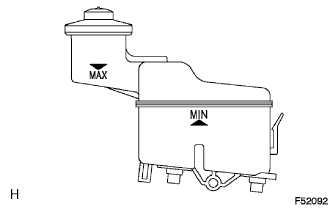
Add brake fluid to keep the level between the MIN and MAX lines of the reservoir while bleeding the clutch line.
Fluid SAE J1703 or FMVSS No. 116 DOT3 -
Remove the bleeder plug cap.
-
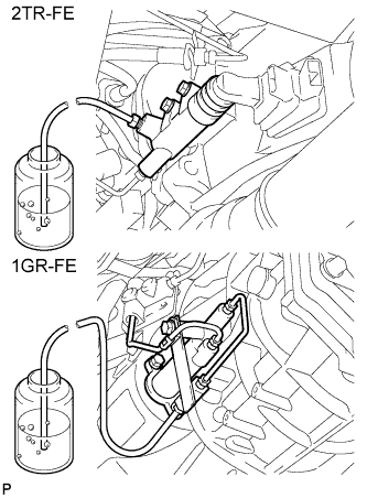
Connect a vinyl tube to the bleeder plug.
-
Depress the clutch pedal several times, and then loosen the bleeder plug with the pedal depressed.
-
At the point when fluid stops coming out, tighten the bleeder plug, and then release the clutch pedal.
-
Repeat the previous 2 steps until all the air in the fluid is completely bled out.
-
Tighten the bleeder plug.
- Torque:
- 11 N*m { 110 kgf*cm, 8 ft.*lbf }
-
Install the bleeder plug cap.
-
Check that all the air has been bled out of the clutch line.
-
Check for brake fluid leaks.
-
Check the brake fluid level in the reservoir Click here.
-
Install the brake master cylinder reservoir filler cap assembly.
-
-
CHECK BRAKE FLUID LEVEL IN RESERVOIR
-
Check the fluid level and add fluid if necessary.
Fluid SAE J1703 or FMVSS No. 116 DOT3 Tech Tips
Add fluid to a level between the reservoir's MIN and MAX lines.
-
-
CHECK FOR BRAKE FLUID LEAKAGE
-
INSTALL REAR WHEEL
- Torque:
- 105 N*m { 1,071 kgf*cm, 77 ft.*lbf }
-
CHECK PARKING BRAKE LEVER TRAVEL
-
Pull the lever upward with a force of approximately 200 N (20 kgf, 45 lbf) and count the number of clicks.
OK 7 to 9 clicks (without rear brake dragging)
-
-
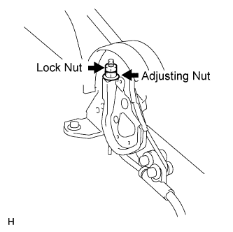
ADJUST PARKING BRAKE LEVER TRAVEL
-
Turn the No. 1 wire adjusting nut until the lever travel is correct.
OK 7 to 9 clicks (without rear brake dragging) <Lever pulling force: approximately 200 N (20 kgf, 45 lbf)> -
Tighten the lock nut.
- Torque:
- 5.2 N*m { 53 kgf*cm, 46 in.*lbf }
Tech Tips
If the lever travel cannot be fully adjusted with this procedure, proceed to the "ADJUST PARKING BRAKE TURN BUCKLE" procedure.
-