POWER STEERING LINK DISASSEMBLY

-
FIX POWER STEERING LINK ASSEMBLY
-
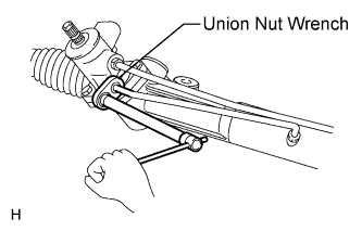
Using a union nut wrench, remove the 2 turn pressure tubes.
-
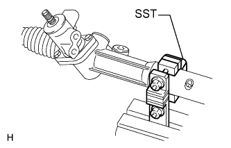
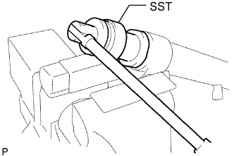
Using SST, fix the steering link between aluminum plates in a vise, as shown in the illustration.
- SST
- 09612-00012
-
-
REMOVE TIE ROD END SUB-ASSEMBLY LH
-
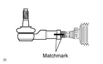
Place matchmarks on the tie rod end, lock nut and rack end.
-
Loosen the lock nut and remove the tie rod end and lock nut.
-
-
REMOVE TIE ROD END SUB-ASSEMBLY RH
Tech Tips
Use the same procedures described for the LH side.
-
REMOVE STEERING RACK BOOT CLAMP LH
-
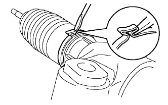
Using pliers and a screwdriver, loosen the clamp.
Tech Tips
Mark the RH and LH boots.
Note
Be careful not to damage the boot.
-
-
REMOVE STEERING RACK BOOT CLAMP RH
Tech Tips
Use the same procedures described for the LH side.
-
REMOVE STEERING RACK BOOT CLIP LH
-
Using pliers, remove the clip.
Note
Be careful not to damage the boot.
-
-
REMOVE STEERING RACK BOOT CLIP RH
Tech Tips
Use the same procedures described for the LH side.
-
REMOVE STEERING RACK BOOT LH
-
REMOVE STEERING RACK BOOT RH
-
REMOVE STEERING RACK END SUB-ASSEMBLY
-
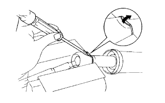
Using a screwdriver and hammer, stake back the washer.
Note
Do not strike the steering rack.
-
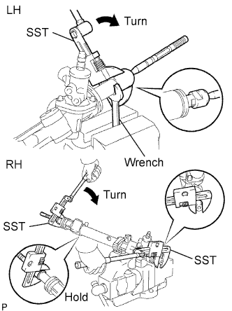
Using a wrench, hold the steering rack (LH side).
-
Using SST, remove the steering rack end (LH side) from the power steering rack.
- SST
- 09922-10010
Note
Rotate SST in the direction shown in the illustration.
-
Using SST, remove the steering rack end (RH side) from the power steering rack.
- SST
- 09922-10010
Note
Rotate SST in the direction shown in the illustration.
-
Remove the 2 claw washers.
-
-
REMOVE RACK GUIDE
-
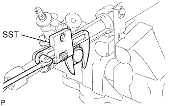
Using SST, remove the lock nut.
- SST
- 09922-10010
-
Remove the claw washer.
Note
Rotate SST in the direction shown in the illustration.
-
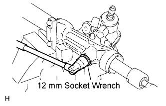
Using a 12 mm socket wrench, remove the rack guide spring cap.
-
Remove the spring and rack guide.
-
-
REMOVE POWER STEERING CONTROL VALVE
-
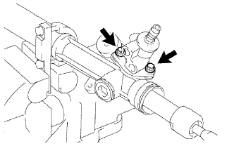
Remove the 2 bolts.
-
Pull out the control valve from the rack housing.
-
Remove the control valve gasket.
-
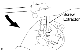
Using a screw extractor, remove the 2 union seats from the control valve housing.
-
-
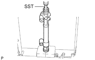
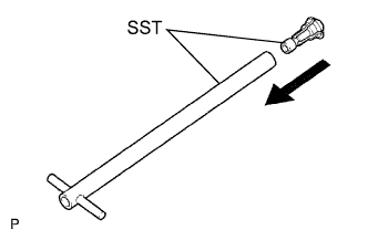
REMOVE CYLINDER END STOPPER
-
Using SST, remove the stopper.
- SST
- 09631-20120
-
-
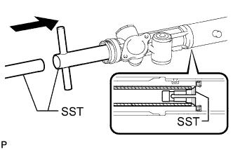
REMOVE STEERING RACK AND OIL SEAL
-
Using SST, press out the steering rack and oil seal.
- SST
- 09950-70010 ( 09951-07200 )
Note
Take care not to drop the steering rack.
-
Remove the oil seal from the steering rack.
-
-
INSPECT POWER STEERING RACK
-
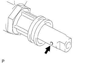
Insert a wire 20 mm (0.79 in.) into the vent hole of the steering rack and ensure that the vent hole is not clogged with grease.
Note
If the hole is clogged, the pressure inside the boot will change after it is assembled and the steering wheel is turned.
-
-
INSPECT TIE ROD END SUB-ASSEMBLY LH
-
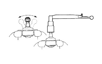
Move the ball joint stud back and forth 5 times as shown in the illustration, before installing the nut.
-
Using a torque wrench, turn the nut continuously at a rate of 2 to 4 seconds per turn and take the torque reading on the 5th turn.
- Torque:
- (turning)
- 0.5 to 3.5 N*m { 5.1 to 35.7 kgf*cm, 0.37 to 2.58 in.*lbf }
-
-
INSPECT TIE ROD END SUB-ASSEMBLY RH
Tech Tips
Use the same procedures described for the LH side.
-
REMOVE STEERING RACK PISTON RING
-
Using a screwdriver, remove the "teflon" ring and O-ring from the steering rack.
Note
Be careful not to damage the groove of the ring.
-
-
REMOVE POWER STEERING CYLINDER TUBE OIL SEAL
-
Install SST (09612-07120) to SST (09612-07210).
- SST
- 09612-70100 ( 09612-07120, 09612-07210 )
Note
-
Lightly apply MP grease to the tip of SST (09612-07230) and inside of SST (09612-07210 and 09612-07120) before use.
-
Completely install SST (09612-07120) to SST (09612-07210) to prevent damage to the inside of the rack housing.
-
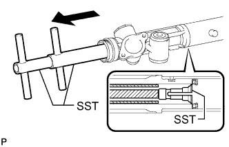
Insert SST (09612-07210) into the rack housing at an angle until it comes in contact with the power steering cylinder tube oil seal. Install SST (09612-07220) to SST (09612-07210).
- SST
- 09612-70100 ( 09612-07120, 09612-07210, 09612-07220 )
Note
Do not damage the inside of the power steering rack housing.
-
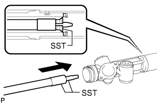
Hold SST (09612-07220) and pull SST (09612-07210) to position SST (09612-07120) the inside of the rack housing.
- SST
- 09612-70100 ( 09612-07120, 09612-07210, 09612-07220, 09612-07230 )
Tech Tips
Make sure that SST (09612-07120) is positioned at the chamfered part between the power steering cylinder tube oil seal and the rack housing.
-
Install SST (09612-07240) to SST (09612-07230). Insert the tip of SST (09612-07230) into the service hole of SST (09612-07120) in the rack housing.
- SST
- 09612-70100 ( 09612-07120, 09612-07230, 09612-07240 )
Note
-
Make sure that SST (09612-07240) is installed to prevent damage to SST (09612-07120).
-
Do not damage the inside of the rack housing.
-
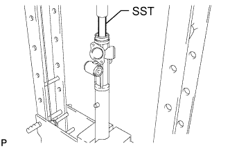
Install SST (09951-07150) to SST (09612-07230). Using a press, remove the power steering cylinder tube oil seal.
- SST
- 09612-70100 ( 09612-07120, 09612-07230, 09612-07240 )
- 09950-70010 ( 09951-07150 )
Note
Do not damage the rack housing.
Tech Tips
Replace SST (09951-07150) with another of different length from the set if necessary.
-