POWER STEERING LINK REMOVAL

-
DISCONNECT CABLE FROM NEGATIVE BATTERY TERMINAL
CAUTION:
Wait at least 90 seconds after disconnecting the cable from the negative (-) battery terminal to prevent airbag and seat belt pretensioner activation.
-
PLACE FRONT WHEEL FACING STRAIGHT AHEAD
-
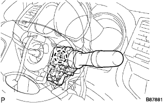
REMOVE STEERING PAD ASSEMBLY
-
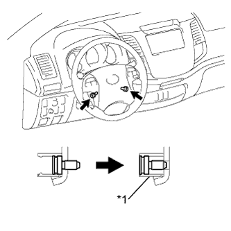
Text in Illustration *1 Screw Case Using a T30 "TORX" socket wrench, loosen the 2 screws until the groove along the screw circumference catches on the screw case.
-
Pull out the steering pad from the steering wheel as shown in the illustration. Then support the steering pad with one hand.
Note
When removing the steering pad, do not pull the airbag wire harness.
-
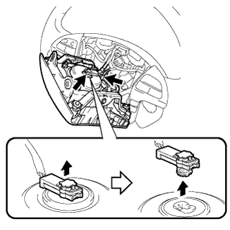
Disconnect the horn connector.
-
Disconnect the connector and remove the steering pad.
Note
When handling the airbag connector, do not damage the airbag wire harness.
-
-
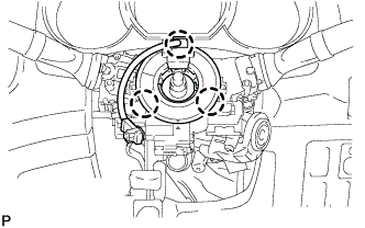
REMOVE STEERING WHEEL ASSEMBLY
-
Remove the steering wheel set nut.
-
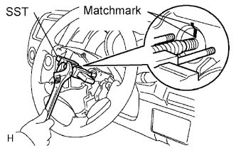
Place matchmarks on the steering wheel and main shaft.
-
Using SST, remove the steering wheel.
- SST
- 09950-50013 ( 09951-05010, 09952-05010, 09953-05020, 09954-05021 )
-
-
REMOVE STEERING COLUMN COVER LOWER
-
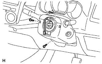
Remove the 3 screws and lower cover.
-
-
REMOVE STEERING COLUMN COVER UPPER
-
REMOVE WINDSHIELD WIPER SWITCH ASSEMBLY
-
Disconnect the connectors.
-
Detach the claw and remove the windshield wiper switch.
Note
Do not push the claw with excessive force as damage may occur.
-
-
REMOVE HEADLIGHT DIMMER SWITCH ASSEMBLY
-
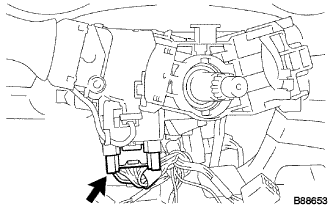
Disconnect the connector.
-
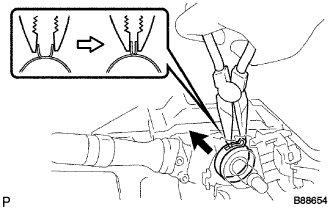
Using needle-nose pliers, remove the band clamp as shown in the illustration.
-
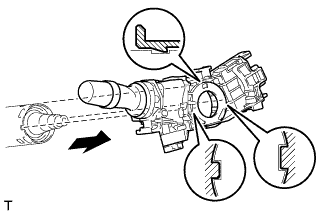
While loosening the band clamp as shown in the illustration, detach the claw to remove the headlight dimmer switch assembly.
Note
If the claw is pressed forcefully, it will break.
-
-
REMOVE SPIRAL CABLE SUB-ASSEMBLY
-
Disconnect the connectors from the spiral cable.
Note
When handling the airbag connector, do not damage the airbag wire harness.
-
Detach the 3 claws and remove the spiral cable.
-
-
REMOVE FRONT WHEEL
-
REMOVE NO. 2 ENGINE UNDER COVER
-
Remove the 4 bolts and under cover.
-
-
REMOVE NO. 1 ENGINE UNDER COVER
-
Remove the 4 bolts and under cover.
-
-
REMOVE FRONT SIDE MEMBER TO FRONT SUSPENSION CROSSMEMBER BRACE
-
Remove the 8 bolts and crossmember brace.
-
-
REMOVE FRONT STABILIZER BAR
-
Remove the stabilizer bar front from the vehicle body.
-
-
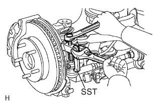
DISCONNECT TIE ROD END SUB-ASSEMBLY LH
-
Remove the cotter pin and nut.
-
Using SST, disconnect the tie rod end from the steering knuckle arm.
- SST
- 09628-62011
-
-
DISCONNECT TIE ROD END SUB-ASSEMBLY RH
Tech Tips
Use the same procedures described for the LH side.
-
DISCONNECT STEERING SLIDING YOKE
-
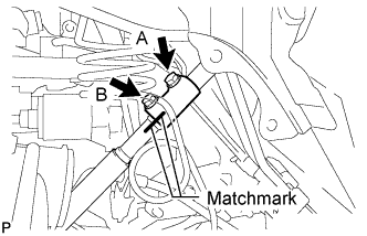
Loosen the bolt labeled A.
-
Make matchmarks on the steering yoke and steering intermediate shaft.
-
Remove the bolt labeled B.
-
Disconnect the steering sliding yoke from the No. 2 steering intermediate shaft.
-
-
REMOVE NO. 2 STEERING INTERMEDIATE SHAFT SUB-ASSEMBLY
-
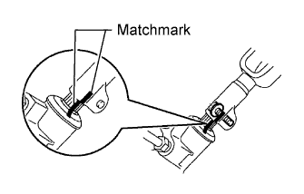
Make matchmarks on the intermediate shaft and steering link.
-
Remove the bolt and intermediate shaft from the steering link.
Note
If the No.2 intermediate shaft is struck, replace it with a new one,
-
-
DISCONNECT PRESSURE FEED TUBE ASSEMBLY
-
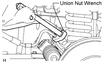
Using a union nut wrench, loosen the flare nut and disconnect the pressure feed tube.
-
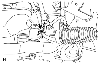
Remove the bolt and disconnect the pressure feed tube from the steering link.
-
-
DISCONNECT STEERING GEAR OUTLET RETURN TUBE
-
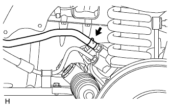
Disengage the clip and disconnect the return hose.
-
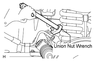
Using a union nut wrench, disconnect the outlet return tube.
-
-
REMOVE POWER STEERING LINK ASSEMBLY
-
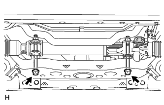
Fix the 2 nuts in place and remove the 2 bolts. Then remove the link from the frame.
Note
Never turn the nut. Be sure to turn the bolt.
Tech Tips
Removal of the link may be easier if the following is performed: 1) remove the differential mount, and 2) slide the differential toward the rear of the vehicle.
-