ANTI-LOCK BRAKE SYSTEM (w/ Rear Differential Lock), Diagnostic DTC:C1249/49

| DTC Code | DTC Name |
|---|---|
| C1249/49 | Open in Stop Light Switch Circuit |
DESCRIPTION
This circuit recognizes brake operation by sending a stop light signal to the skid control ECU.
| DTC No. | DTC Detection Condition | Trouble Area |
|---|---|---|
| C1249/49 | Both conditions continue for at least 0.3 seconds:
|
|
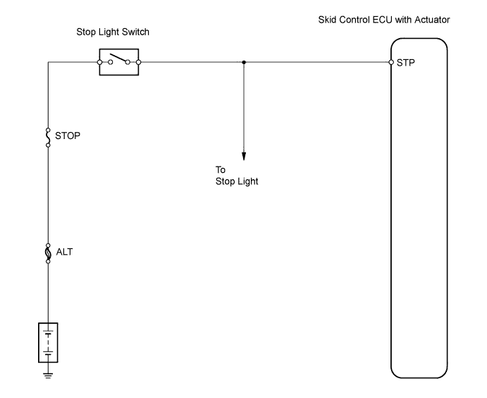
WIRING DIAGRAM
INSPECTION PROCEDURE
PROCEDURE
-
CHECK STOP LIGHT SWITCH (OPERATION)
-
Check that the stop light illuminates when the brake pedal is depressed, and turns off when the brake pedal is released.
OK Condition Stop Light Condition Brake pedal depressed Illuminates Brake pedal released Turns off
NG 
INSPECT STOP LIGHT SWITCH ASSEMBLY Click here
OK 
-
-
CHECK WIRE HARNESS (SKID CONTROL ECU - STOP LIGHT SWITCH)
-
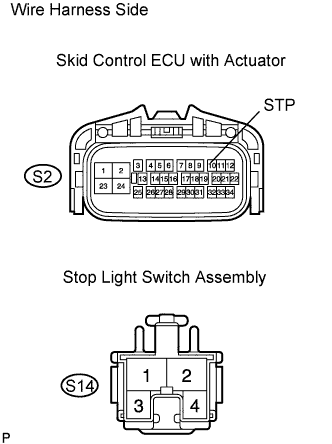
Disconnect the S2 ECU connector.
-
Disconnect the S14 stop light switch connector.
-
Measure the resistance of the wire harness side connectors.
Standard resistance Tester Connection Specified Condition S2-10 (STP) - S14-1 Below 1 Ω
NG 
REPAIR OR REPLACE HARNESS AND CONNECTOR
OK
-
-
CHECK IF DTC OUTPUT RECURS
-
Clear the DTCs.
-
Drive the vehicle at approximately 30 km/h (19 mph) or more for 60 seconds or more.
-
Check for DTCs.
Result Result Proceed to DTC is output A DTC is not output B
B
END
A 
REPLACE BRAKE ACTUATOR ASSEMBLY
-
-
INSPECT STOP LIGHT SWITCH ASSEMBLY
-
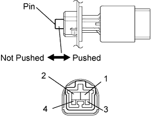
Disconnect the switch connector.
-
Measure the resistance of the stop light switch.
Standard resistance Tester Connection Switch Condition Specified Condition 1 - 2 Pin not pushed Below 1 Ω 1 - 2 Pin pushed 10 kΩ or higher 3 - 4 Pin not pushed 10 kΩ or higher 3 - 4 Pin pushed Below 1 Ω
NG
REPLACE STOP LIGHT SWITCH ASSEMBLY
OK
-
-
CHECK WIRE HARNESS (SKID CONTROL ECU - BATTERY)
-
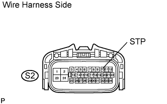
Disconnect the S2 ECU connector.
-
Measure the voltage of the wire harness side connector.
Standard voltage Tester Connection Condition Specified Condition S2-10 (STP) - Body ground Brake pedal depressed 8 to 14 V S2-10 (STP) - Body ground Brake pedal released Below 1 V
NG
REPAIR OR REPLACE HARNESS AND CONNECTOR
OK
-
-
CHECK IF DTC OUTPUT RECURS
-
Clear the DTCs.
-
Drive the vehicle at approximately 30 km/h (19 mph) or more for 60 seconds or more.
-
Check for DTCs.
Result Result Proceed to DTC is output A DTC is not output B
B
END
A
REPLACE BRAKE ACTUATOR ASSEMBLY
-