ANTI-LOCK BRAKE SYSTEM TC and CG Terminal Circuit
DESCRIPTION
Connecting terminals TC and CG of the DLC3 causes the ECU to display DTCs through ABS warning light blinking patterns.
WIRING DIAGRAM
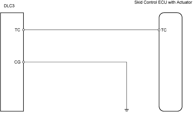
INSPECTION PROCEDURE
PROCEDURE
-
CHECK WIRE HARNESS (DLC3 - SKID CONTROL ECU AND BODY GROUND)
-
Disconnect the S2 ECU connector.
-
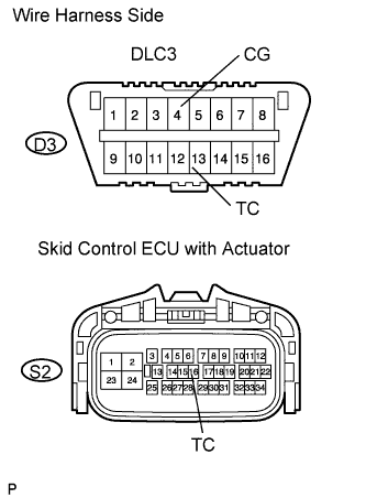
Measure the resistance of the wire harness side connectors.
Standard resistance Tester Connection Specified Condition D3-4 (CG) - Body ground Below 1 Ω D3-13 (TC) - S2-16 (TC) Below 1 Ω S2-16 (TC) - Body ground 10 kΩ or higher
NG 
REPAIR OR REPLACE HARNESS AND CONNECTOR
OK 
REPLACE BRAKE ACTUATOR ASSEMBLY
-