ANTI-LOCK BRAKE SYSTEM ABS Warning Light Remains ON
DESCRIPTION
When checking for a 2 digit DTC, the ABS warning light may remain on.
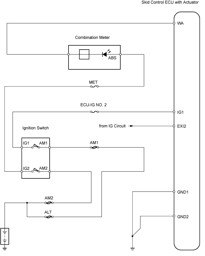
WIRING DIAGRAM
INSPECTION PROCEDURE
PROCEDURE
-
CHECK FOR DTC
-
Turn the ignition switch ON.
-
Check that the ABS warning light illuminates.
-
Check if the same DTCs are recorded.
Result Result Proceed to DTC is not output (when using intelligent tester) A DTC is not output (when not using intelligent tester) B DTC is output C
B 
INSPECT SKID CONTROL ECU CONNECTOR Click here
C 
REPAIR CIRCUIT INDICATED BY OUTPUT DTC
A 
-
-
INSPECT SKID CONTROL ECU CONNECTOR
-
Check that each ECU connector is properly installed.
OK Each ECU connector is properly installed.
NG
CONNECT CONNECTOR TO ECU CORRECTLY
OK
-
-
READ VALUE USING INTELLIGENT TESTER (ECU IG POWER VOLTAGE)
-
Using the Data List, check for proper functioning of the ECU IG power voltage.
Skid control ECU Tester Display Measurement Item/Range Normal Condition Diagnostic Note ECU IG Power Voltage ECU power supply voltage / too Low, Normal or too High Normal - Result Result Proceed to Display is Normal A Display is not Normal B
B
CHECK WIRE HARNESS (SKID CONTROL ECU - BATTERY) Click here
A
-
-
CHECK WIRE HARNESS (SKID CONTROL ECU - BATTERY)
-
Disconnect the S2 ECU connector.
-
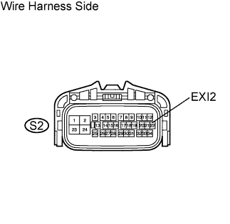
Measure the voltage of the wire harness side connector.
Standard voltage Tester Connection Condition Specified Condition S2-22 (EXI2) - Body ground Ignition switch ON 10 to 14 V
NG
REPAIR OR REPLACE HARNESS AND CONNECTOR
OK
-
-
CHECK ABS WARNING LIGHT
-
Disconnect the S2 ECU connector.
-
Turn the ignition switch ON.
-
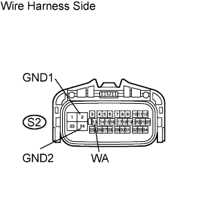
Using a service wire, connect terminal WA to GND1 or GND2 of the S2 ECU connector. Check the ABS warning light.
OK ABS warning light turns off. -
Turn the ignition switch OFF.
-
Remove the service wire.
-
Turn the ignition switch ON. Check the ABS warning light.
OK ABS warning light illuminates.
OK
REPLACE BRAKE ACTUATOR ASSEMBLY
NG
-
-
CHECK WIRE HARNESS (SKID CONTROL ECU - COMBINATION METER AND BODY GROUND)
-
Disconnect the S2 ECU connector.
-
Disconnect the C27 meter connector.
-
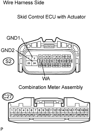
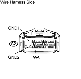
Measure the resistance of the wire harness side connectors.
Standard resistance Tester Connection Specified Condition S2-13 (WA) - C27-38 Below 1 Ω S2-13 (WA) - Body ground 10 kΩ or higher S2-2 (GND1) - Body ground Below 1 Ω S2-24 (GND2) - Body ground Below 1 Ω
NG
REPAIR OR REPLACE HARNESS AND CONNECTOR
OK 
REPLACE COMBINATION METER ASSEMBLY
-
-
INSPECT SKID CONTROL ECU CONNECTOR
-
Check that each ECU connector is properly installed.
OK Each ECU connector is properly installed.
NG
CONNECT CONNECTOR TO ECU CORRECTLY
OK
-
-
CHECK WIRE HARNESS (SKID CONTROL ECU - BATTERY)
-
Disconnect the S2 ECU connector.
-
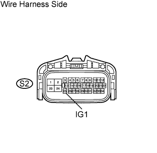
Measure the voltage of the wire harness side connector.
Standard voltage Tester Connection Condition Specified Condition S2-25 (IG1) - Body ground Ignition switch ON 10 to 14 V
NG
REPAIR OR REPLACE HARNESS AND CONNECTOR
OK
-
-
CHECK ABS WARNING LIGHT
-
Disconnect the S2 ECU connector.
-
Turn the ignition switch ON.
-
Using a service wire, connect terminal WA to GND1 or GND2 of the S2 ECU connector. Check the ABS warning light.
OK ABS warning light turns off. -
Turn the ignition switch OFF.
-
Remove the service wire.
-
Turn the ignition switch ON. Check the ABS warning light.
OK ABS warning light illuminates.
OK
REPLACE BRAKE ACTUATOR ASSEMBLY
NG
-
-
CHECK WIRE HARNESS (SKID CONTROL ECU - COMBINATION METER AND BODY GROUND)
-
Disconnect the S2 ECU connector.
-
Disconnect the C27 meter connector.
-
Measure the resistance of the wire harness side connectors.
Standard resistance Tester Connection Specified Condition S2-13 (WA) - C27-38 Below 1 Ω S2-13 (WA) - Body ground 10 kΩ or higher S2-2 (GND1) - Body ground Below 1 Ω S2-24 (GND2) - Body ground Below 1 Ω
NG
REPAIR OR REPLACE HARNESS AND CONNECTOR
OK
REPLACE COMBINATION METER ASSEMBLY
-
-
CHECK WIRE HARNESS (SKID CONTROL ECU - BATTERY)
-
Disconnect the S2 ECU connector.
-
Measure the voltage of the wire harness side connector.
Standard voltage Tester Connection Condition Specified Condition S2-25 (IG1) - Body ground Ignition switch ON 10 to 14 V
NG
REPAIR OR REPLACE HARNESS AND CONNECTOR
OK
REPLACE BRAKE ACTUATOR ASSEMBLY
-