FRONT WHEEL ALIGNMENT ADJUSTMENT

-
INSPECT TIRE
-
INSPECT VEHICLE HEIGHT
Note
Before inspecting the wheel alignment, adjust the vehicle height to the specification.
-
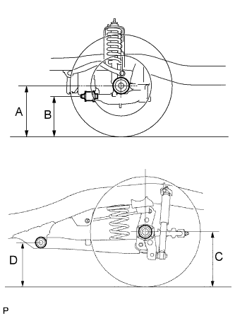
Press down on the vehicle several times to stabilize the suspension, and measure the vehicle height.
Standard Vehicle height (Unloaded Vehicle) Vehicle Model Front A - B Rear C - D GGN50L-EKASKV 76 mm (2.99 in.) 61 mm (2.40 in.) GGN50L-EKMSKV 75 mm (2.95 in.) 60 mm (2.36 in.) GGN50L-NKASKV 76 mm (2.99 in.) 61 mm (2.40 in.) GGN50L-NKMSKV 75 mm (2.95 in.) 60 mm (2.36 in.) TGN51L-EKMSKV 76 mm (2.99 in.) 59 mm (2.32 in.) TGN51L-EKPSKV 78 mm (3.07 in.) 59 mm (2.32 in.) TGN51L-NKMSKV 76 mm (2.99 in.) 59 mm (2.32 in.) TGN51L-NKPSKV 78 mm (3.07 in.) 59 mm (2.32 in.) TGN61L-EKMSKV 71 mm (2.80 in.) 56 mm (2.20 in.) TGN61L-EKPSKV 73 mm (2.87 in.) 56 mm (2.20 in.) TGN61L-NKMSKV 71 mm (2.80 in.) 56 mm (2.20 in.) TGN61L-NKPSKV 73 mm (2.87 in.) 56 mm (2.20 in.) GGN50L-NKASKZ 76 mm (2.99 in.) 61 mm (2.40 in.) TGN51L-NKPSKZ 78 mm (3.07 in.) 59 mm (2.32 in.) Measuring point A Ground clearance of front wheel center B Ground clearance of lower suspension arm No. 1 set bolt center C Ground clearance of rear wheel center D Ground clearance of strut rod set bolt center
-
If the vehicle height is not as specified, press down on the vehicle several times to stabilize the suspension. Then measure the vehicle height again.
Note
The standard value shown here is a value that is used for adjusting the wheel alignment and does not indicate the height of an actual vehicle.
-
-
-
INSPECT TOE-IN
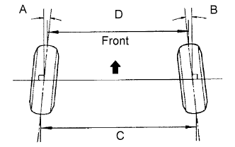
Standard Toe-in (Unloaded Vehicle) Vehicle Model Front A + B
Rear C - D
GGN50L-EKASKV A + B: 0°1' +/-5' (0.02°+/-0.09°)
C - D: 0.4 +/-1.0 mm (0.02 +/-0.04 in.)
GGN50L-EKMSKV A + B: 0°2' +/-5' (0.03°+/-0.09°)
C - D: 0.6 +/-1.0 mm (0.02 +/-0.04 in.)
GGN50L-NKASKV A + B: 0°1' +/-5' (0.02°+/-0.09°)
C - D: 0.4 +/-1.0 mm (0.02 +/-0.04 in.)
GGN50L-NKMSKV A + B: 0°2' +/-5' (0.03°+/-0.09°)
C - D: 0.6 +/-1.0 mm (0.02 +/-0.04 in.)
TGN51L-EKMSKV A + B: 0°1' +/-5' (0.02°+/-0.09°)
C - D: 0.5 +/-1.0 mm (0.02 +/-0.04 in.)
TGN51L-EKPSKV A + B: 0°1' +/-5' (0.01°+/-0.09°)
C - D: 0.2 +/-1.0 mm (0.01 +/-0.04 in.)
TGN51L-NKMSKV A + B: 0°1' +/-5' (0.02°+/-0.09°)
C - D: 0.5 +/-1.0 mm (0.02 +/-0.04 in.)
TGN51L-NKPSKV A + B: 0°1' +/-5' (0.01°+/-0.09°)
C - D: 0.2 +/-1.0 mm (0.01 +/-0.04 in.)
TGN61L-EKMSKV A + B: 0°3' +/-5' (0.05°+/-0.09°)
C - D: 1.3 +/-1.0 mm (0.05 +/-0.04 in.)
TGN61L-EKPSKV A + B: 0°2' +/-5' (0.04°+/-0.09°)
C - D: 1.0 +/-1.0 mm (0.04 +/-0.04 in.)
TGN61L-NKMSKV A + B: 0°3' +/-5' (0.05°+/-0.09°)
C - D: 1.3 +/-1.0 mm (0.05 +/-0.04 in.)
TGN61L-NKPSKV A + B: 0°2' +/-5' (0.04°+/-0.09°)
C - D: 1.0 +/-1.0 mm (0.04 +/-0.04 in.)
GGN50L-NKASKZ A + B: 0°1' +/-5' (0.02°+/-0.09°)
C - D: 0.4 +/-1.0 mm (0.02 +/-0.04 in.)
TGN51L-NKPSKZ A + B: 0°1' +/-5' (0.01°+/-0.09°)
C - D: 0.2 +/-1.0 mm (0.01 +/-0.04 in.)
-
If the toe-in is not as specified, adjust it at the rack ends.
-
-
ADJUST TOE-IN
-
Detach the rack boot set clips.
-
Loosen the tie rod end lock nuts.
-
Turn the right and left rack ends by an equal amount to adjust the toe-in to the center value.
Tech Tips
The toe-in should be as close as possible to the center value.
-
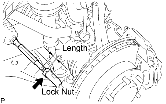
Make sure that the lengths of the right and left rack ends are approximately the same.
Standard difference 0 +/-1 mm (0 +/-0.039 in.) -
Tighten the tie rod end lock nuts.
- Torque:
- 56 N*m { 566 kgf*cm, 41 ft.*lbf }
-
Place the boots on the seats and attach the clips.
Tech Tips
Make sure that the boots are not twisted.
-
-
INSPECT WHEEL ANGLE
-
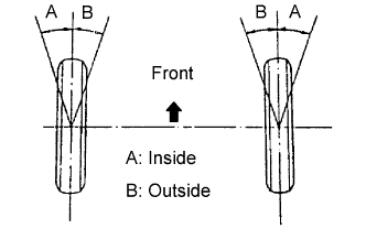
Turn the steering wheel to the left and right full lock positions, and measure the wheel angle.
Standard Wheel Angle (Unloaded Vehicle) For All Tire Sizes except 265/65R17 Inside Wheel Angle Outside Wheel Angle (Reference) 36°18' (34°18' to 37°18')
(36.3°(34.3° to 37.3°))
33°12'
(33.2°)
For Tire Size 265/65R17 Inside Wheel Angle Outside Wheel Angle (Reference) 34°42' (32°42' to 35°42')
(34.7°(32.7° to 35.7°))
31°54'
(31.9°)
-
If the angles are not as specified, check and adjust the right and left rack end lengths.
-
-
-
INSPECT CAMBER, CASTER AND STEERING AXIS INCLINATION
-
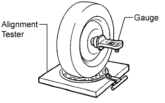
Install a camber-caster-kingpin gauge or place the front wheels on the center of a wheel alignment tester.
-
Inspect the camber, caster and steering axis inclination.
Standard Camber Inclination (Unloaded Vehicle) Vehicle Model Camber Inclination GGN50L-EKASKV
Right-left error
0°9' +/-30' (0.15°+/-0.50°)
30' (0.50°) or less
GGN50L-EKMSKV
Right-left error
0°11' +/-30' (0.18°+/-0.50°)
30' (0.50°) or less
GGN50L-NKASKV
Right-left error
0°9' +/-30' (0.15°+/-0.50°)
30' (0.50°) or less
GGN50L-NKMSKV
Right-left error
0°11' +/-30' (0.18°+/-0.50°)
30' (0.50°) or less
TGN51L-EKMSKV
Right-left error
0°10' +/-30' (0.17°+/-0.50°)
30' (0.50°) or less
TGN51L-EKPSKV
Right-left error
0°8' +/-30' (0.13°+/-0.50°)
30' (0.50°) or less
TGN51L-NKMSKV
Right-left error
0°10' +/-30' (0.17°+/-0.50°)
30' (0.50°) or less
TGN51L-NKPSKV
Right-left error
0°8' +/-30' (0.13°+/-0.50°)
30' (0.50°) or less
TGN61L-EKMSKV
Right-left error
0°16' +/-30' (0.27°+/-0.50°)
30' (0.50°) or less
TGN61L-EKPSKV
Right-left error
0°14' +/-30' (0.23°+/-0.50°)
30' (0.50°) or less
TGN61L-NKMSKV
Right-left error
0°16' +/-30' (0.27°+/-0.50°)
30' (0.50°) or less
TGN61L-NKPSKV
Right-left error
0°14' +/-30' (0.23°+/-0.50°)
30' (0.50°) or less
GGN50L-NKASKZ
Right-left error
0°9' +/-30' (0.15°+/-0.50°)
30' (0.50°) or less
TGN51L-NKPSKZ
Right-left error
0°8' +/-30' (0.13°+/-0.50°)
30' (0.50°) or less
Standard Caster Inclination (Unloaded Vehicle) Vehicle Model Caster Inclination GGN50L-EKASKV
Right-left error
2°57' +/-30' (2.95°+/-0.50°)
30' (0.50°) or less
GGN50L-EKMSKV
Right-left error
2°55' +/-30' (2.92°+/-0.50°)
30' (0.50°) or less
GGN50L-NKASKV
Right-left error
2°57' +/-30' (2.95°+/-0.50°)
30' (0.50°) or less
GGN50L-NKMSKV
Right-left error
2°55' +/-30' (2.92°+/-0.50°)
30' (0.50°) or less
TGN51L-EKMSKV
Right-left error
2°53' +/-30' (2.88°+/-0.50°)
30' (0.50°) or less
TGN51L-EKPSKV
Right-left error
2°55' +/-30' (2.92°+/-0.50°)
30' (0.50°) or less
TGN51L-NKMSKV
Right-left error
2°53' +/-30' (2.88°+/-0.50°)
30' (0.50°) or less
TGN51L-NKPSKV
Right-left error
2°55' +/-30' (2.92°+/-0.50°)
30' (0.50°) or less
TGN61L-EKMSKV
Right-left error
2°50' +/-30' (2.83°+/-0.50°)
30' (0.50°) or less
TGN61L-EKPSKV
Right-left error
2°51' +/-30' (2.85°+/-0.50°)
30' (0.50°) or less
TGN61L-NKMSKV
Right-left error
2°50' +/-30' (2.83°+/-0.50°)
30' (0.50°) or less
TGN61L-NKPSKV
Right-left error
2°51' +/-30' (2.85°+/-0.50°)
30' (0.50°) or less
GGN50L-NKASKZ
Right-left error
2°57' +/-30' (2.95°+/-0.50°)
30' (0.50°) or less
TGN51L-NKPSKZ
Right-left error
2°55' +/-30' (2.92°+/-0.50°)
30' (0.50°) or less
Standard Steering Axis Inclination (Unloaded Vehicle) Vehicle Model Steering Axis Inclination GGN50L-EKASKV
Right-left error
12°20' +/-30' (12.33°+/-0.50°)
30' (0.50°) or less
GGN50L-EKMSKV
Right-left error
12°18' +/-30' (12.30°+/-0.50°)
30' (0.50°) or less
GGN50L-NKASKV
Right-left error
12°20' +/-30' (12.33°+/-0.50°)
30' (0.50°) or less
GGN50L-NKMSKV
Right-left error
12°18' +/-30' (12.30°+/-0.50°)
30' (0.50°) or less
TGN51L-EKMSKV
Right-left error
12°19' +/-30' (12.32°+/-0.50°)
30' (0.50°) or less
TGN51L-EKPSKV
Right-left error
12°21' +/-30' (12.35°+/-0.50°)
30' (0.50°) or less
TGN51L-NKMSKV
Right-left error
12°19' +/-30' (12.32°+/-0.50°)
30' (0.50°) or less
TGN51L-NKPSKV
Right-left error
12°21' +/-30' (12.35°+/-0.50°)
30' (0.50°) or less
TGN61L-EKMSKV
Right-left error
12°13' +/-30' (12.22°+/-0.50°)
30' (0.50°) or less
TGN61L-EKPSKV
Right-left error
12°15' +/-30' (12.25°+/-0.50°)
30' (0.50°) or less
TGN61L-NKMSKV
Right-left error
12°13' +/-30' (12.22°+/-0.50°)
30' (0.50°) or less
TGN61L-NKPSKV
Right-left error
12°15' +/-30' (12.25°+/-0.50°)
30' (0.50°) or less
GGN50L-NKASKZ
Right-left error
12°20' +/-30' (12.33°+/-0.50°)
30' (0.50°) or less
TGN51L-NKPSKZ
Right-left error
12°21' +/-30' (12.35°+/-0.50°)
30' (0.50°) or less
-
If the camber and caster are not as specified, adjust them.
-
If the steering axis inclination is not as specified after the camber and caster have been correctly adjusted, check the steering knuckle and front wheel for distortion or looseness.
-
-
-
ADJUST CAMBER AND CASTER
Note
After the camber has been adjusted, inspect the toe-in.
-
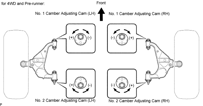
Loosen the camber adjusting cam nut and camber adjusting cam bolt.
-
Turn the No. 1 camber adjusting cam and No. 2 camber adjusting cam in both directions, and adjust the camber and caster to the center value.
-
The camber and caster should be as close as possible to the center value.
-
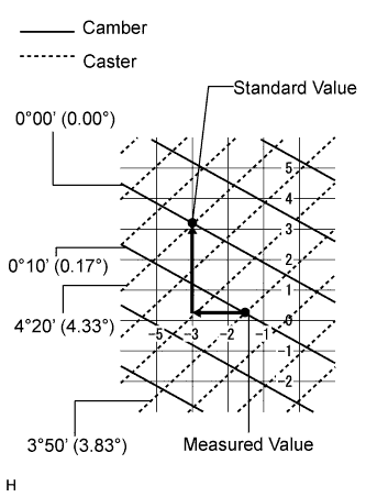
How to read the adjustment chart (using examples).
-
Find the standard wheel alignment value applicable for the particular model.
-
Mark the selected standard value on the adjustment chart.
Standard Value (Reference) Camber Caster 0°00' (0.00°) 4°20' (4.33°) -
Mark the alignment value on the adjustment chart as measured when the vehicle is unloaded.
Measured Value (Reference) Camber Caster 0°10' (0.17°) 3°50' (3.83°) -
As shown in the chart, read the distance from the marked point to 0, and adjust the front and/or rear adjusting cams accordingly.
Amount To Turn Adjusting Cams (by gradation) No. 1 Camber Adjusting Cam No. 2 Camber Adjusting Cam +3.0 mm -1.5 mm 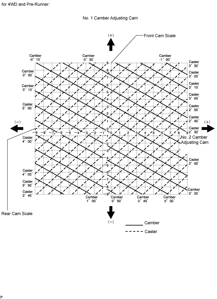
-
-