REAR AXLE SHAFT REMOVAL

Tech Tips
-
Use the same procedures for the RH side and LH side.
-
The procedures listed below are for the LH side.
-
DISCONNECT CABLE FROM NEGATIVE BATTERY TERMINAL
CAUTION:
Wait at least 90 seconds after disconnecting the cable from the negative (-) battery terminal to prevent airbag and seat belt pretensioner activation.
-
REMOVE REAR WHEEL
-
DRAIN BRAKE FLUID
Note
Wash off brake fluid immediately if it comes in contact with any painted surface.
-
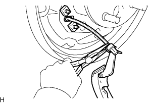
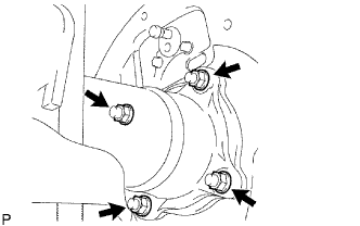
DISCONNECT BRAKE LINE
-
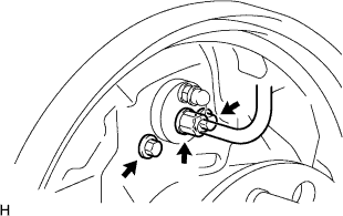
Using a union nut wrench, disconnect the brake line.
-
Remove the 2 bolts and cylinder.
-
-
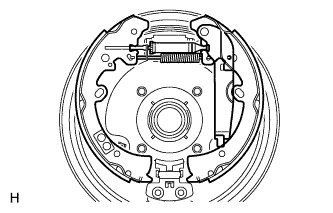
REMOVE REAR BRAKE DRUM SUB-ASSEMBLY
-
Release the parking brake lever, and remove the drum and gasket.
Tech Tips
If the drum cannot be removed easily, perform the following procedures.
-
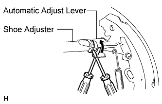
Remove the hole plug (adjust) and insert a screwdriver into the hole on the backing plate, and hold the automatic adjust lever away from the adjuster.
-
Using another screwdriver, compress the shoe adjuster by turning the adjusting wheel.
-
-
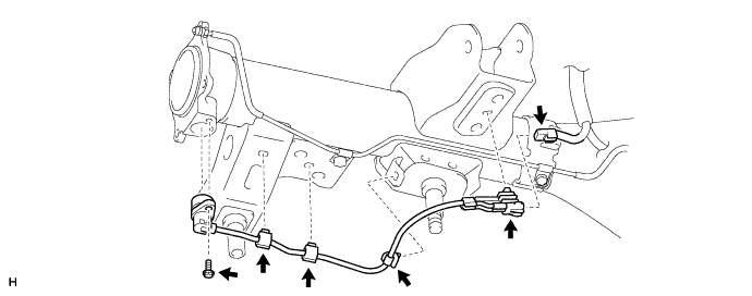
REMOVE REAR SPEED SENSOR LH (w/ ABS)
-
Disconnect the connector.
-
Detach the connector.
-
Detach the 3 clamps.
-
Remove the bolt and speed sensor.
Note
Keep the sensor tip and sensor installation hole free from foreign matter.
-
-
REMOVE BRAKE SHOES
-
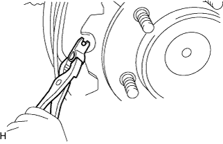
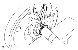
Using pliers, remove the 2 shoe hold down springs, 2 pins, front brake shoe and rear brake shoe.
-
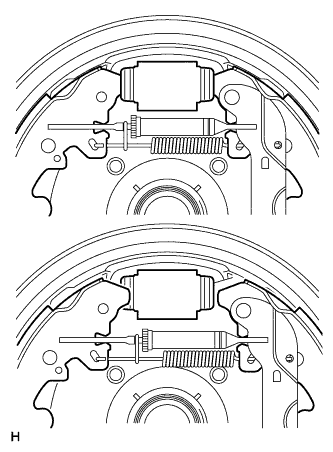
Push the front or rear side of the wheel brake cylinder with the brake shoe. Then remove the side of the brake shoe opposite to the side of the cylinder being pushed. Finally, remove the remaining side of the brake shoe.
Note
Be careful not to damage the cylinder dust boot.
-
Move one of the shoes downward and remove the shoe tension spring.
-
Remove the brake shoe front and rear side.
-
Remove the strut set and return spring from the shoe.
-
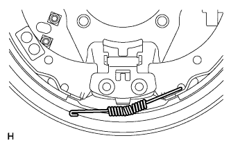
Remove the support clip from the strut set and return spring.
-
Using needle-nose pliers, disconnect the No. 3 parking brake cable from the parking brake shoe lever.
-
-
DISCONNECT PARKING BRAKE CABLE
-
Remove the 2 bolts and disconnect the parking brake cable.
-
-
REMOVE REAR AXLE SHAFT WITH BACKING PLATE
-
Remove the 4 nuts.
-
Pull out the axle shaft from the axle housing.
-
-
REMOVE O-RING
-
Remove the O-ring from the axle housing.
-
-
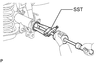
REMOVE REAR AXLE SHAFT OIL SEAL LH
-
Using SST, tap out the oil seal.
- SST
- 09308-00010
Note
Be careful not to damage the axle housing hole.
-
-
REMOVE BACKING PLATE TO REAR AXLE HOUSING SETTING BOLT
-
Temporarily install 4 nuts to the setting bolts.
Note
Do not use any nuts removed from the vehicle, as they may be damaged.
-
Using a hammer, tap out the 4 setting bolts from the backing plate.
-
Remove the 4 nuts and 4 setting bolts.
-
-
REMOVE REAR AXLE BEARING INNER RETAINER LH AND REAR SKID CONTROL ROTOR (w/ ABS)
-
Grind the retainer and skid control rotor surfaces using a grinder, and then pry them off with a chisel and hammer.
Note
Be careful not to damage the axle shaft.
-
-
REMOVE REAR AXLE BEARING INNER RETAINER LH
-
Using a snap ring expander, remove the snap ring.
-
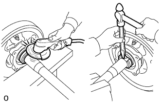
Grind the retainer surface using a grinder, and then pry it off with a chisel and hammer.
Note
Be careful not to damage the axle shaft.
-
Remove the shaft washer from the axle shaft.
-
-
REMOVE REAR AXLE SHAFT LH
-
Insert the setting bolts into the backing plate and temporarily install washers and nuts to the setting bolts. Tighten the nuts to temporarily install the setting bolts to the backing plate and bearing case and bearing case.
-
Remove the nuts and washers from the setting bolts.
-
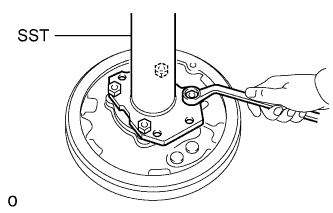
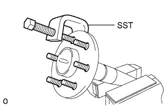
Install SST to the backing plate with the 4 nuts.
- SST
- 09521-25011
-
Using SST and a press, press out the axle shaft.
-
Remove the 4 nuts and SST.
-
Temporarily install 4 nuts to the setting bolts.
Note
Do not use any nuts removed from the vehicle, as they may be damaged.
-
Using a hammer, tap out the 4 setting bolts from the backing plate.
-
Remove the 4 nuts and 4 setting bolts.
-
-
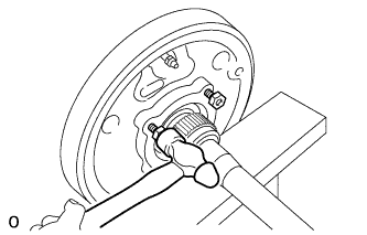
REMOVE REAR AXLE HUB BOLT LH
-
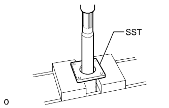
Secure the axle shaft between aluminum plates in a vise.
-
Using SST, remove the 6 hub bolts.
- SST
- 09650-17011
-
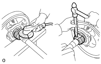
Remove the deflector and gasket from the axle shaft.
Note
-
Do not deform the deflector.
-
Make sure to align the groove of SST with the flange of the oil deflector.
-
-
-
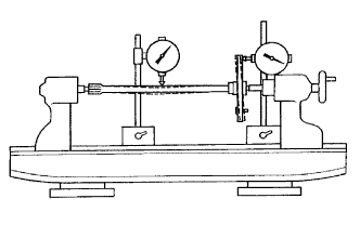
INSPECT REAR AXLE SHAFT LH
-
Using a dial indicator, measure the rear axle shaft shaft runout and flange runout.
Maximum runout Item Specified Condition Shaft runout 1.5 mm (0.0591 in.) Flange runout 0.10 mm (0.00394 in.) If the rear axle shaft or flange is damaged or worn, or if the runout is greater than the maximum, replace the rear axle shaft.
-
-
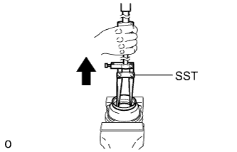
REMOVE REAR AXLE SHAFT OUTER OIL SEAL
-
Using SST, tap out the outer oil seal.
- SST
- 09308-00010
-
-
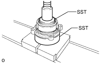
REMOVE REAR AXLE SHAFT BEARING LH
-
Using SST and a press, press out the bearing.
- SST
- 09223-56010
- 09950-60010 ( 09951-00640 )
-