DIFFERENTIAL CARRIER ASSEMBLY (for DANA Made) DISASSEMBLY

-
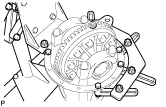
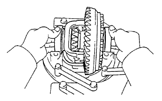
FIX REAR DIFFERENTIAL CARRIER ASSEMBLY
-
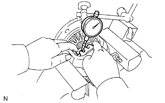
INSPECT RUNOUT OF REAR DRIVE PINION COMPANION FLANGE SUB-ASSEMBLY REAR
-
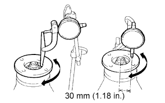
Using a dial indicator, measure the runout of the companion flange vertically and laterally.
Maximum runout Runout Maximum Vertical runout 0.10 mm (0.0039 in.) Lateral runout 0.10 mm (0.0039 in.)
-
If the runout is greater than the maximum, replace the companion flange.
-
-
-
INSPECT RUNOUT OF DIFFERENTIAL RING GEAR
-
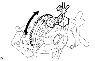
Using a dial indicator, measure the runout of the ring gear.
Maximum runout 0.07 mm (0.0028 in.)
-
If the runout is greater than the maximum, replace the ring gear with a new one.
-
-
-
INSPECT DIFFERENTIAL RING GEAR BACKLASH
-
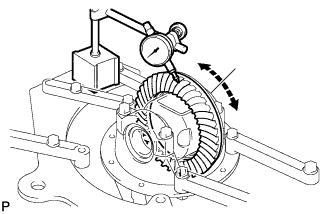
Using a dial indicator, measure the backlash of the ring gear.
Standard backlash 0.13 to 0.18 mm (0.0051 to 0.0071 in.)
-
If the backlash is not within the specification, adjust the side bearing preload or repair as necessary.
Tech Tips
Perform the measurements at 3 or more positions around the side bearing preload.
-
-
-
INSPECT DIFFERENTIAL DRIVE PINION PRELOAD
-
Using a torque wrench, measure the preload of backlash between the drive pinion and ring gear.
Standard drive pinion preload (at start of torque) 0.56 to 0.85 N*m (6 to 9 kgf*cm, 4.9 to 7.5 in.*lbf)
-
If necessary, disassemble and inspect the differential.
-
-
-
INSPECT TOTAL PRELOAD
-
Using a torque wrench, measure the preload with the teeth of the drive pinion and ring gear in contact.
-
Using a torque wrench, measure the total preload.
Tech Tips
A bolt without a torque specification is shown in the service data Click here.
-
If necessary, disassemble and inspect the differential.
-
-
-
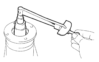
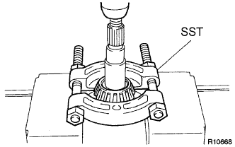
REMOVE REAR DRIVE PINION NUT
-
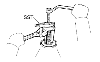
Using SST and a hammer, loosen the staked part of the nut.
- SST
- 09930-00010 ( 09931-00010, 09931-00020 )
-
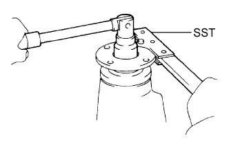
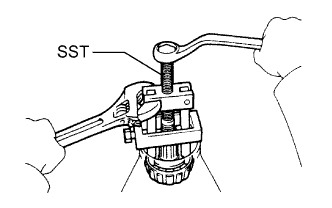
Using SST to hold the companion flange in place, remove the nut.
- SST
- 09330-00021 ( 09330-00030 )
-
-
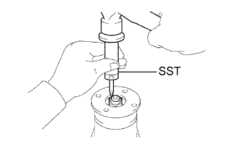
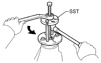
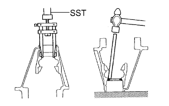
REMOVE REAR DRIVE PINION COMPANION FLANGE SUB-ASSEMBLY
-
Using SST, remove the companion flange.
- SST
- 09950-30012 ( 09951-03010, 09953-03010, 09954-03010, 09955-03030, 09956-03040 )
Note
Before using SST (center bolt), apply hypoid gear oil to its threads and tip.
-
-
REMOVE REAR DIFFERENTIAL DUST DEFLECTOR
-
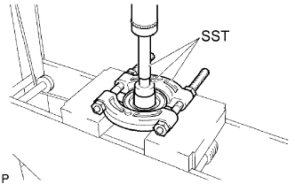
Using SST and a press, press out the dust deflector.
- SST
- 09950-60010 ( 09951-00380 )
- 09950-70010 ( 09951-07150 )
- 09950-00020
Note
Do not drop the companion flange.
-
-
REMOVE REAR DIFFERENTIAL CARRIER OIL SEAL
-
Using SST, remove the oil seal from the differential carrier.
- SST
- 09308-10010
-
-
REMOVE REAR DIFFERENTIAL DRIVE PINION OIL SLINGER
-
REMOVE REAR DRIVE PINION FRONT TAPERED ROLLER BEARING
-
Using SST, remove the roller bearing (inner) from the drive pinion.
- SST
- 09556-22010
-
-
REMOVE DIFFERENTIAL CASE ASSEMBLY
-
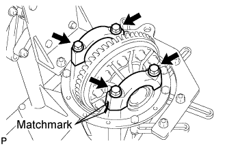
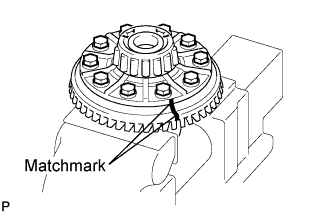
Place matchmarks on the bearing cap and differential carrier.
-
Remove the 4 bolts and 2 differential bearing caps.
-
Remove the 2 side shims.
-
Remove the rear differential case assembly from the differential carrier.
Tech Tips
Tag the 2 case bearing outer races to show the location for reassembly.
-
-
REMOVE DIFFERENTIAL DRIVE PINION
-
Remove the drive pinion and bearing spacer from the differential carrier.
-
-
REMOVE REAR DRIVE PINION REAR TAPERED ROLLER BEARING
-
Using SST and a press, press out the roller bearing (inner) from the drive pinion.
- SST
- 09950-00020
Note
Do not drop the drive pinion.
Tech Tips
If the drive pinion or ring gear is damaged, replace them as a set.
-
-
REMOVE REAR DIFFERENTIAL DRIVE PINION PLATE WASHER
-
REMOVE REAR DRIVE PINION FRONT TAPERED ROLLER BEARING
-
Using SST, remove the roller bearing (outer) from the carrier.
- SST
- 09308-00010
-
Using a brass bar and hammer, tap out the oil storage ring from the carrier.
Tech Tips
If the bearing is damaged during removal, replace it.
-
-
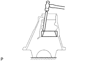
REMOVE REAR DRIVE PINION REAR TAPERED ROLLER BEARING
-
Using a brass bar and hammer, tap out the rear tapered roller bearing (outer) from the carrier.
Tech Tips
If the bearing is damaged during removal, replace it.
-
-
REMOVE DIFFERENTIAL RING GEAR
-
Place matchmarks on the ring gear and differential case.
-
Remove the 10 ring gear set bolts.
-
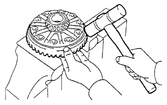
Using a plastic-faced hammer, tap on the ring gear to separate it from the differential case.
-
-
INSPECT DIFFERENTIAL CASE ASSEMBLY RUNOUT
-
Install the rear differential case bearing to the differential case.
-
Install the differential case to the differential carrier.
-
Install the 2 bearing caps to the differential carrier with the 4 bolts.
- Torque:
- 85 N*m { 867 kgf*cm, 63 ft.*lbf }
-
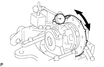
Using a dial indicator, measure the differential case runout.
Maximum runout 0.07 mm (0.0028 in.) -
Remove the differential case.
-
Remove the rear differential case bearing.
-
-
REMOVE REAR DIFFERENTIAL CASE BEARING
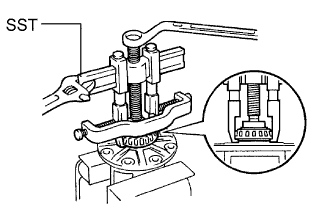
-
Using SST, remove the 2 bearings from the differential case.
- SST
- 09950-40011 ( 09951-04020, 09952-04010, 09953-04030, 09954-04010, 09955-04061, 09957-04010, 09958-04011 )
- 09950-60010 ( 09951-00360 )
Tech Tips
Do not remove the case bearing when not replacing the differential case.
-
-
INSPECT DIFFERENTIAL PINION AND SIDE GEAR
-
Check that the differential pinion and differential side gear are not worn.
-
If the differential pinion or differential side gear is not worn, replace the differential.
-
-
-
INSPECT DIFFERENTIAL CASE
-
Measure the side gear backlash.
-
Using a dial indicator, measure the side gear backlash while holding one pinion gear toward the differential case.
Standard backlash 0.05 to 0.20 mm (0.0020 to 0.008 in.)
-
If the backlash is not within the specified range, replace the differential case with a new one.
-
-
-