DIFFERENTIAL CARRIER ASSEMBLY (w/ Differential Lock) REASSEMBLY

-
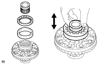
ASSEMBLE DIFFERENTIAL CASE
-
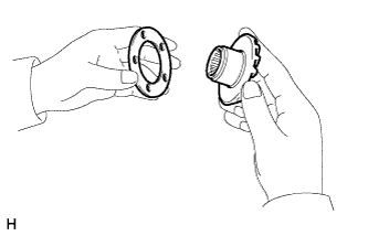
Install the side gear thrust washer to the side gear.
-
Install the 4 rear differential pinion gear thrust washers to the 4 rear drive pinion gears.
-
Install the 4 rear differential pinion gear thrust washers and 4 rear drive pinion gears to the spider.
-
Secure the differential case RH.
-
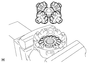
Install the rear differential side gear and rear differential spider to the differential case RH.
-
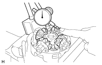
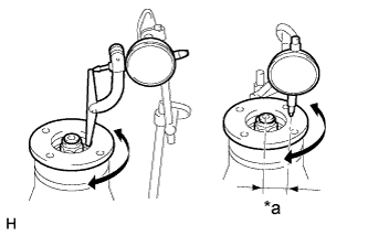
Using a dial indicator, measure the differential case RH backlash while holding the pinion toward the case.
Standard backlash 0.05 to 0.20 mm (0.00197 to 0.00787 in.) -
Remove the rear differential spider from the differential case RH.
-
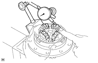
Install the rear differential side gear and rear differential spider to the differential case LH.
-
Using a dial indicator, measure the differential case LH backlash while holding the pinion toward the case.
Standard backlash 0.05 to 0.20 mm (0.00197 to 0.00787 in.) Tech Tips
Using the table below, select 2 thrust washers which will ensure that the backlash is within the specifications.
Standard Washer Thickness Thickness mm (in.) Thickness mm (in.) 0.88 to 0.92 (0.0347 to 0.0362) 1.18 to 1.22 (0.0465 to 0.0480) 0.98 to 1.02 (0.0386 to 0.0401) 1.28 to 1.32 (0.0504 to 0.0519) 1.08 to 1.12 (0.0426 to 0.0440) - -
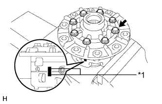
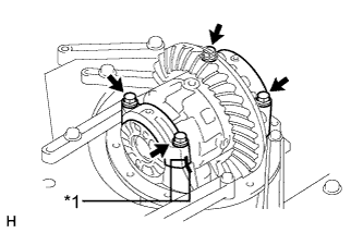
Text in Illustration *1 Matchmark Align the matchmarks and assemble the RH and LH cases.
-
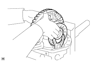
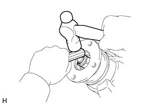
Using a plastic-faced hammer, install the differential case.
-
Install the 8 bolts.
- Torque:
- 54 N*m { 547 kgf*cm, 40 ft.*lbf }
-
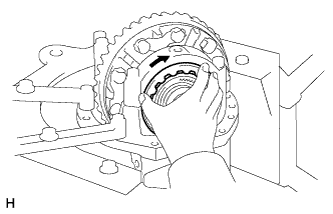
Install the rear differential lock sleeve to the differential case LH.
-
-
INSTALL DIFFERENTIAL RING GEAR
-
Clean the contact surfaces of the differential case and ring gear.
-
Heat the ring gear in boiling water that is approximately 100°C (212°F).
-
Carefully remove the ring gear from the boiling water.
-
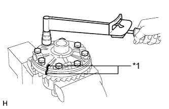
Text in Illustration *1 Matchmark After the moisture on the ring gear has completely evaporated, quickly align the matchmarks on the ring gear and differential case and install the ring gear to the differential case.
-
Temporarily install 5 new lock plates and the 10 bolts.
-
After the ring gear cools down, diametrically tighten the 10 bolts uniformly in several passes.
- Torque:
- 87 N*m { 891 kgf*cm, 64 ft.*lbf }
-
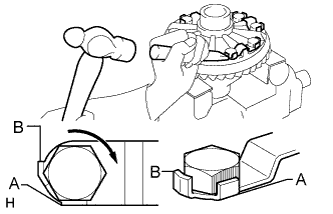
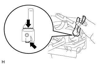
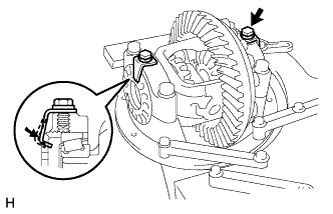
Using a chisel and hammer, stake the 5 lock plates.
Tech Tips
Strike the tab labeled A so that it is flush with the flat surface of the bolt. Strike the tab labeled B so that half of the tab contacts the bolt as shown in the illustration.
-
-
INSTALL REAR DIFFERENTIAL CASE BEARING
-
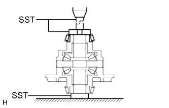
Using SST and a press, press the 2 case bearings (inner) onto the differential case.
- SST
- 09950-60010 ( 09951-00560, 09951-00570 )
- 09950-70010 ( 09951-07150 )
-
-
INSPECT DIFFERENTIAL RING GEAR RUNOUT
-
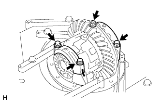
Install the differential case and 2 case bearings (outer) to the carrier, and install the 2 adjusting nuts so that there is no play in the bearing.
-
Install the 2 bearing caps with the 4 bolts.
- Torque:
- 85 N*m { 870 kgf*cm, 63 ft.*lbf }
-
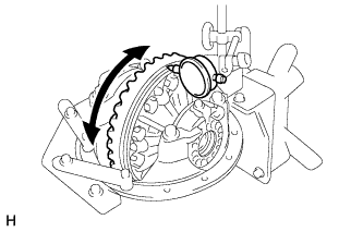
Using a dial indicator, measure the runout of the ring gear.
Maximum runout 0.07 mm (0.00276 in.) If the runout exceeds the specified maximum value, remove the ring gear and check the runout of the differential case.
-
Remove the 4 bolts, 2 bearing caps, 2 adjusting nuts and differential case.
-
-
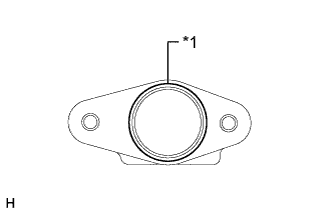
INSTALL DIFFERENTIAL OIL STORAGE RING
-
Using a brass bar and hammer, tap in a new oil storage ring.
Note
Be careful not to damage the oil storage ring.
-
-
INSTALL REAR DRIVE PINION FRONT TAPERED ROLLER BEARING
-
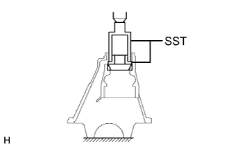
Using SST and a press, press the bearing (outer) into the carrier.
- SST
- 09316-60011 ( 09316-00011, 09316-00021 )
-
-
INSTALL REAR DRIVE PINION REAR TAPERED ROLLER BEARING
-
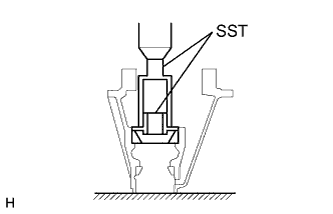
Using SST and a press, press the bearing (outer) into the carrier.
- SST
- 09316-60011 ( 09316-00011, 09316-00041 )
-
-
INSTALL REAR DRIVE PINION REAR TAPERED ROLLER BEARING
-
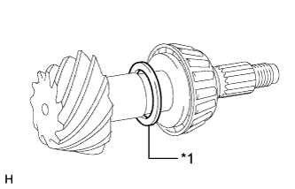
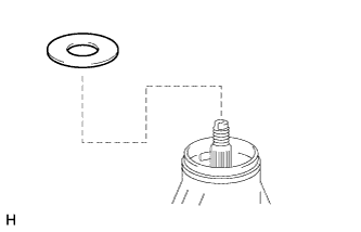
Install the plate washer to the drive pinion.
Tech Tips
First, install a washer that has the same thickness as the removed washer. After checking the tooth contact pattern, replace the washer with one of a different thickness if necessary.
-
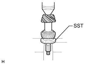
Using SST and a press, press the bearing (inner) onto the drive pinion.
- SST
- 09506-30012
-
-
ADJUST DIFFERENTIAL DRIVE PINION PRELOAD
-
Install the drive pinion, bearing (inner) and oil slinger.
Tech Tips
Install the spacer and oil seal after adjusting the gear contact pattern.
-
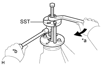
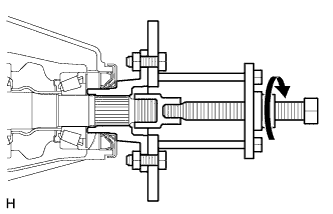
Text in Illustration *a Turn *b Hold Using SST, install the companion flange.
- SST
- 09950-30012 ( 09951-03010, 09953-03010, 09954-03010, 09955-03030, 09956-03040 )
Tech Tips
Before using SST (center bolt), apply hypoid gear oil to its threads and tip.
-
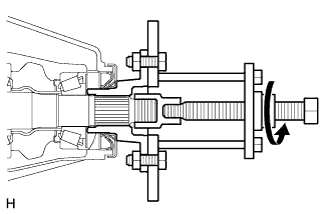
Adjust the drive pinion preload by installing the drive pinion nut.
-
Using SST to hold the companion flange in place, tighten the nut.
- SST
- 09330-00021 ( 09330-00030 )
- Torque:
- 370 N*m { 3773 kgf*cm, 273 ft.*lbf, or less }
Note
-
As there is no spacer, tighten a little at a time. Be careful not to overtighten the nut.
-
Apply hypoid gear oil LSD to drive pinion thread and nut seat face.
-
Using a torque wrench, measure the preload.
Standard Drive Pinion Preload (Starting Torque) Bearing Specified Condition New bearing 1.0 to 1.5 N*m (11 to 15 kgf*cm, 9 to 13 in.*lbf) Reused bearing 0.5 to 0.7 N*m (6 to 7 kgf*cm, 5 to 6 in.*lbf) Note
-
For a more accurate measurement, rotate the bearing forward and backward several times before measuring.
-
Record the differential drive pinion preload for the total preload measurement.
-
-
-
INSTALL DIFFERENTIAL CASE ASSEMBLY
-
Apply MP grease to the rack of the shift fork and connecting part of the indicator switch.
Text in Illustration 
MP grease -
Insert the shift fork into the differential carrier as shown in the illustration.
-
Place the outer race and adjusting nut on the left side of the sleeve.
Tech Tips
Check that the sleeve moves smoothly.
-
Insert the shift fork into the groove of the sleeve while holding the sleeve by hand, and install the case to the carrier.
Tech Tips
Make sure that there is backlash between the ring gear and drive pinion.
-
-
INSTALL REAR DIFFERENTIAL BEARING ADJUSTING NUT
-
Install the 2 adjusting nuts to the carrier, making sure the nuts are threaded properly.
-
-
INSPECT AND ADJUST DIFFERENTIAL RING GEAR AND DIFFERENTIAL DRIVE PINION BACKLASH
-
Text in Illustration *1 Matchmark Align the matchmarks on the cap and carrier.
-
Install the right and left bearing caps with the 4 bolts.
- Torque:
- 85 N*m { 870 kgf*cm, 63 ft.*lbf }
-
If the bearing cap does not fit tightly on the carrier, the adjusting nuts are not threaded properly.
Tech Tips
Reinstall the adjusting nuts if necessary.
-
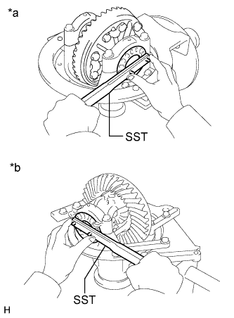
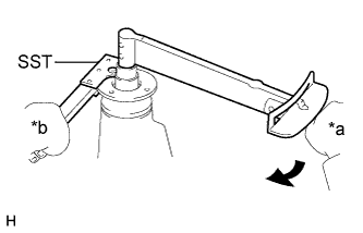
Text in Illustration *a for LH Side *b for RH Side Loosen the 4 bearing cap bolts to the point where the adjusting nuts can be turned by SST.
-
Using SST, tighten the adjusting nut on the ring gear side until the ring gear has a backlash of about 0.2 mm (0.00787 in.).
- SST
- 09504-00011
- 09960-10010 ( 09962-01000, 09963-00700 )
-
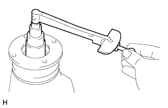
While turning the ring gear, use SST to tighten the adjusting nut on the drive pinion side. After the bearings have settled, loosen the adjusting nut on the drive pinion side.
- SST
- 09504-00011
- 09960-10010 ( 09962-01000, 09963-00700 )
-
Using SST, tighten the adjusting nut 1 to 1.5 notches from the 0 preload position.
-
Using a dial indicator, adjust the ring gear backlash until it is within the specification.
Standard backlash 0.13 to 0.18 mm (0.00512 to 0.00708 in.) Tech Tips
-
The backlash is adjusted by turning the left and right adjusting nuts by an equal amount. For example, loosen the nut on the right side one notch and loosen the nut on the left side one notch.
-
Perform the measurement at 3 or more positions around the circumference of the ring gear.
-
-
Tighten the bearing cap bolts.
- Torque:
- 85 N*m { 870 kgf*cm, 63 ft.*lbf }
-
-
INSPECT TOTAL PRELOAD
-
Using a torque wrench, measure the preload with the teeth of the drive pinion and ring gear in contact.
Standard Total Preload Bearing Specified Condition New 0.4 to 0.5 N*m (4 to 6 kgf*cm, 4 to 5 in.*lbf) + drive pinion preload Reused 0.4 to 0.5 N*m (4 to 6 kgf*cm, 4 to 5 in.*lbf) + drive pinion preload If the result is not as specified, adjust the preload.
Note
Record the differential ring gear preload.
-
-
INSPECT TOOTH CONTACT BETWEEN RING GEAR AND DRIVE PINION
-
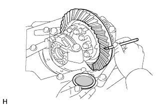
Coat 3 or 4 teeth at 3 different positions on the ring gear with Prussian blue.
-
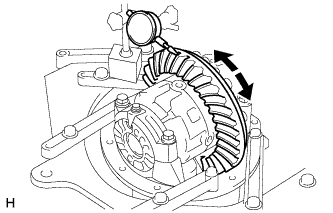
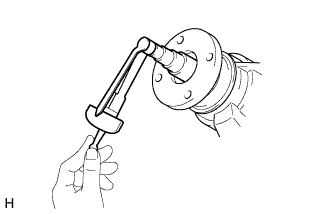
Hold the companion flange firmly in place and rotate the ring gear in both directions.
-
Inspect the tooth contact pattern.
-
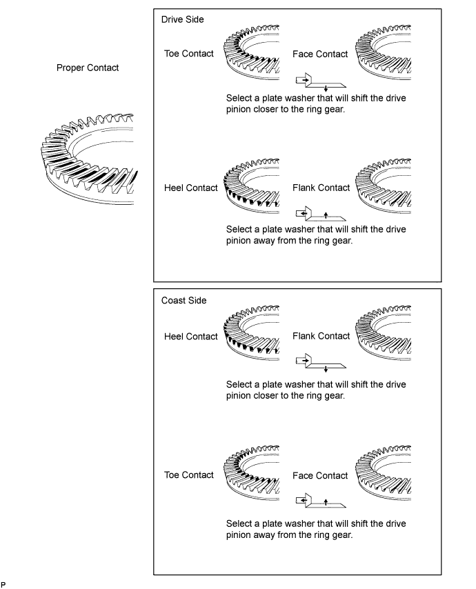
-
Text in Illustration *1 Plate Washer If the teeth are not contacting properly, use the following chart to select a proper washer.
Standard Plate Washer Thickness Thickness mm (in.) Thickness mm (in.) 1.69 to 1.71 (0.0666 to 0.0673) 2.02 to 2.04 (0.0796 to 0.0803) 1.72 to 1.74 (0.0678 to 0.0685) 2.05 to 2.07 (0.0807 to 0.0814) 1.75 to 1.77 (0.0689 to 0.0696) 2.08 to 2.10 (0.0819 to 0.0826) 1.78 to 1.80 (0.0701 to 0.0708) 2.11 to 2.13 (0.0831 to 0.0838) 1.81 to 1.83 (0.0713 to 0.0720) 2.14 to 2.16 (0.0843 to 0.0850) 1.84 to 1.86 (0.0725 to 0.0732) 2.17 to 2.19 (0.0855 to 0.0862) 1.87 to 1.89 (0.0737 to 0.0744) 2.20 to 2.22 (0.0867 to 0.0874) 1.90 to 1.92 (0.0748 to 0.0755) 2.23 to 2.25 (0.0878 to 0.0885) 1.93 to 1.95 (0.0760 to 0.0767) 2.26 to 2.28 (0.0890 to 0.0897) 1.96 to 1.98 (0.0772 to 0.0779) 2.29 to 2.31 (0.0902 to 0.0909) 1.99 to 2.01 (0.0784 to 0.0791) 2.32 to 2.34 (0.0914 to 0.0921)
-
-
-
REMOVE REAR DRIVE PINION NUT
-
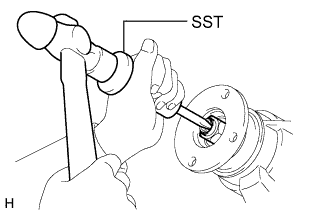
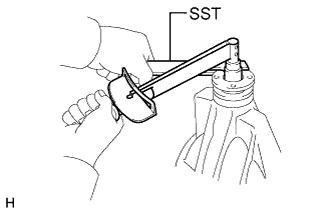
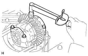
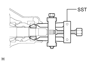
Using SST and a hammer, loosen the staked part of the nut.
- SST
- 09930-00010 ( 09931-00010, 09931-00020 )
-
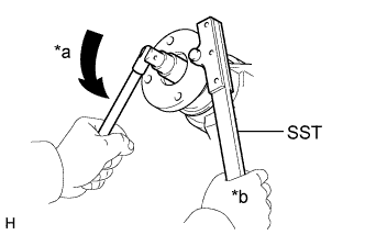
Text in Illustration *a Turn *b Hold Using SST to hold the companion flange in place, remove the nut.
- SST
- 09330-00021 ( 09330-00030 )
-
-
REMOVE REAR DRIVE PINION COMPANION FLANGE SUB-ASSEMBLY WITH DUST DEFLECTOR
-
Using SST, remove the companion flange with dust deflector.
- SST
- 09950-30012 ( 09951-03010, 09953-03010, 09954-03010, 09955-03030, 09956-03040 )
Note
Before using SST (center bolt), apply hypoid gear oil to its threads and tip.
-
-
REMOVE REAR DIFFERENTIAL DRIVE PINION OIL SLINGER
-
Remove the oil slinger from the drive pinion.
-
-
REMOVE REAR DRIVE PINION FRONT TAPERED ROLLER BEARING
-
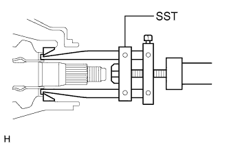
Using SST, remove the roller bearing (inner).
- SST
- 09556-22010
-
Using SST, tap out the roller bearing (outer).
- SST
- 09308-00010
-
-
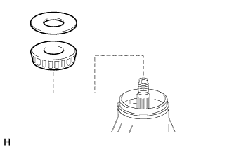
INSTALL REAR DIFFERENTIAL DRIVE PINION BEARING SPACER
-
Install a new bearing spacer.
Tech Tips
Make sure the spacer is installed correctly.
-
-
INSTALL REAR DRIVE PINION FRONT TAPERED ROLLER BEARING
-
Install the bearing (inner) to the drive pinion.
-
-
INSTALL REAR DIFFERENTIAL DRIVE PINION OIL SLINGER
-
Install the oil slinger to the drive pinion.
-
-
INSTALL REAR DIFFERENTIAL CARRIER OIL SEAL
-
Apply MP grease to the lip of the oil seal.
-
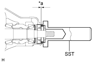
Text in Illustration *a Oil Seal Depth Using SST and a hammer, tap in a new seal.
- SST
- 09554-30011
Standard oil seal depth 0 +/-0.3 mm (0 +/-0.0118 in.)
-
-
INSTALL REAR DRIVE PINION COMPANION FLANGE SUB-ASSEMBLY WITH DUST DEFLECTOR
-
Using SST, install the companion flange with dust deflector.
- SST
- 09950-30012 ( 09951-03010, 09953-03010, 09954-03010, 09955-03030, 09956-03040 )
Note
Before using SST (center bolt), apply hypoid gear oil to its threads and tip.
-
Apply hypoid gear oil LSD to drive pinion thread and nut seat face.
-
Text in Illustration *1 Turn *1 Hold Using SST to hold the companion flange in place, install a new nut.
- SST
- 09330-00021 ( 09330-00030 )
- Torque:
- 370 N*m { 3773 kgf*cm, 273 ft.*lbf, or less }
-
-
INSPECT TOTAL PRELOAD
-
Using a torque wrench, measure the preload with the teeth of the drive pinion and ring gear in contact.
-
Using a torque wrench, measure the total preload.
Standard Total Preload Bearing Specified Condition New bearing 1.1 to 1.6 N*m (12 to 16 kgf*cm, 10 to 14 in.*lbf) + ring gear preload Reused bearing 0.6 to 0.8 N*m (7 to 8 kgf*cm, 6 to 7 in.*lbf) + ring gear preload
-
If necessary, disassemble and inspect the differential.
-
-
-
INSPECT DIFFERENTIAL RING GEAR BACKLASH
-
Using a dial indicator, measure the backlash of the ring gear.
Standard backlash 0.13 to 0.18 mm (0.00512 to 0.00708 in.)
-
If the backlash is not within the specification, adjust the side bearing preload or perform repairs as necessary.
Tech Tips
Perform the measurement at 3 or more positions around the circumference of the ring gear.
-
-
-
INSPECT REAR DRIVE PINION COMPANION FLANGE SUB-ASSEMBLY
-
Text in Illustration *a 30 mm (1.18 in.) Using a dial indicator, measure the runout of the companion flange vertically and laterally.
Maximum Runout Item Specified Condition Vertical runout 0.10 mm (0.00394 in.) Lateral runout 0.10 mm (0.00394 in.)
-
If the runout is more than the maximum, replace the companion flange.
-
-
-
STAKE DRIVE PINION NUT
-
Using a chisel and hammer, stake the nut.
-
-
INSTALL REAR DIFFERENTIAL BEARING ADJUSTING NUT LOCK
-
Install 2 new adjusting nut locks to the bearing caps with the 2 bolts.
- Torque:
- 13 N*m { 130 kgf*cm, 9 ft.*lbf }
-
Bend the nut locks.
-
-
INSTALL REAR DIFFERENTIAL LOCK SHIFT FORK SHAFT
-
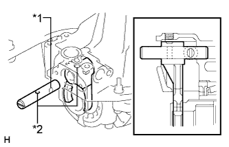
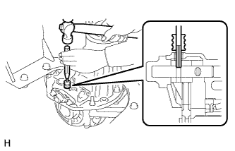
Text in Illustration *1 Groove *2 Hole Apply MP grease to the outer circuit of the fork shaft.
-
Install the fork shaft so that the hole of the shift fork aligns with that of the shift fork shaft.
-
Text in Illustration *1 Seal packing Remove any seal packing material.
Note
Be careful not to drop oil on the contact surface of the differential carrier and shaft retainer.
-
Apply seal packing to the carrier as shown in the illustration.
Seal packing Toyota Genuine Seal Packing 1281, Three Bond 1281 or equivalent Tech Tips
Install the shaft retainer within 3 minutes after applying seal packing.
-
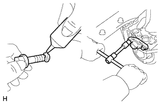
Clean the threads of the bolts and retainer bolts holes with toluene or trichloroethylene.
-
Apply adhesive to 2 or 3 threads at the end of the mounting bolt.
Adhesive Toyota Genuine Adhesive 1344, Three Bond 1344 or equivalent -
Tighten the shaft retainer with the 2 bolts.
- Torque:
- 23 N*m { 237 kgf*cm, 17 ft.*lbf }
-
Using a 5 mm pin punch and hammer, tap in the slotted spring pin to the shift fork.
-
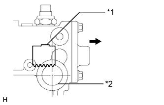
Text in Illustration *1 Lock Shift the fork to the lock side.
-
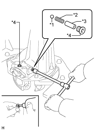
Text in Illustration *1 Steel Ball *2 Spring *3 Spring Seat *4 Screw Plug Install the steel ball, spring and spring seat.
-
Clean the threads of the 2 plug holes with toluene or trichloroethylene.
-
Apply adhesive to the plug threads.
Adhesive Toyota Genuine Adhesive 1344, Three Bond 1344 or equivalent -
Using a 6 mm hexagon wrench, install the screw plugs.
- Torque:
- 23 N*m { 237 kgf*cm, 17 ft.*lbf }
-
-
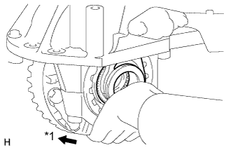
INSPECT REAR DIFFERENTIAL LOCK SLEEVE
-
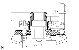
Measure the distance between the sleeve and tip of the differential case when the differential is free, and when it is locked.
Standard Distance Position Specified Condition Lock 17.44 to 18.86 mm (0.6866 to 0.7425 in.) Free 32.40 to 33.90 mm (1.2756 to 1.3346 in.)
-
-
INSTALL NO. 4 TRANSFER INDICATOR SWITCH
-
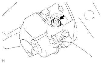
Install the indicator switch and a new gasket.
- Torque:
- 40 N*m { 410 kgf*cm, 30 ft.*lbf }
-
Connect the connector.
-
-
INSTALL DIFFERENTIAL LOCK SHIFT ACTUATOR
-
Text in Illustration *1 Shift Fork *2 Actuator Installation Hole Outside Install a new O-ring to the actuator.
-
Install the actuator with the bolt and nut.
- Torque:
- for Bolt
- 27 N*m { 270 kgf*cm, 20 ft.*lbf }
- for Nut
- 22 N*m { 224 kgf*cm, 16 ft.*lbf }
-
Check that the outermost rack tooth of the shift fork is almost directly above the center line of the actuator installation hole.
-
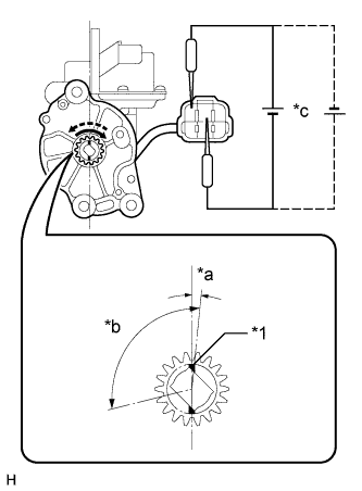
Text in Illustration *1 Matchmark *a 5° *b 108° *c 1.5 V Check that the matchmarks on the pinion of the actuator are in the range between 2 and 8° clockwise of the center line of the actuator.
Note
-
If the matchmarks are not within the specified range, use dry cell batteries to rotate the pinion until the matchmarks are within the range.
-
Do not apply positive (+) battery voltage directly between terminals.
-
If the matchmarks come to the limit of the rotation range, do not apply any more voltage.
-
-
Install a new O-ring to the actuator.
-
Apply a light coat of gear oil to the O-ring.
-
Apply MP grease to the gear parts.
-
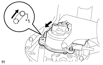
Text in Illustration *1 Knock Pin Check that the outermost rack tooth of the shift fork aligns with the matchmarks on the pinion of the actuator.
-
Install the actuator so that the long hole in the actuator fits with the knock pin on the carrier.
Tech Tips
Do not damage the O-ring of the actuator.
-
Rotate the actuator counterclockwise so that the knock pin slides to the end of the hole as shown in the illustration.
-
Install the bolts.
- Torque:
- 27 N*m { 270 kgf*cm, 20 ft.*lbf }
-
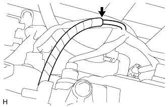
Connect the breather hose.
-
Connect the connector.
-