FRONT LOWER SUSPENSION ARM INSTALLATION

Tech Tips
-
Use the same procedures for the RH side and LH side.
-
The procedures listed below are for the LH side.
-
A bolt without a torque specification is shown in the standard bolt chart Click here.
-
INSTALL FRONT LOWER BALL JOINT ATTACHMENT LH
-
Install the ball joint attachment with the nut and a new cotter pin.
- Torque:
- 140 N*m { 1,428 kgf*cm, 103 ft.*lbf }
-
-
TEMPORARILY INSTALL FRONT LOWER SUSPENSION ARM SUB-ASSEMBLY LH
-
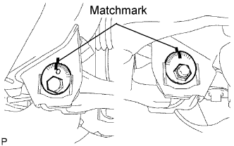
Temporarily install the lower arm with the 2 camber adjusting cams, No. 1 and No. 2 camber adjusting cams and 2 nuts.
-
Align the matchmarks on the No. 1 camber adjusting cam and No. 2 camber adjusting cams. Temporarily tighten the 2 cams and nuts.
-
Install the ball joint attachment with the nut and a new cotter pin.
- Torque:
- 140 N*m { 1,428 kgf*cm, 103 ft.*lbf }
-
Install the ball joint attachment with the 2 bolts.
- Torque:
- 160 N*m { 1,632 kgf*cm, 118 ft.*lbf }
-
-
TEMPORARILY INSTALL FRONT SHOCK ABSORBER WITH COIL SPRING
-
Install the shock absorber with coil spring with the bolt, and temporarily install the nut.
-
-
INSTALL FRONT WHEEL
- Torque:
- 105 N*m { 1,071 kgf*cm, 77 ft.*lbf }
-
STABILIZE SUSPENSION
-
Lower the vehicle.
-
Press down on the vehicle several times to stabilize the suspension.
-
-
TIGHTEN FRONT LOWER SUSPENSION ARM SUB-ASSEMBLY LH
-
Tighten the 2 nuts.
- Torque:
- 140 N*m { 1,428 kgf*cm, 103 ft.*lbf }
-
-
TIGHTEN FRONT SHOCK ABSORBER WITH COIL SPRING
-
Fix the nut in place and tighten the bolt.
- Torque:
- 95 N*m { 969 kgf*cm, 70 ft.*lbf }
Note
Do not tighten the nut.
-
-
INSPECT AND ADJUST FRONT WHEEL ALIGNMENT