FRONT PROPELLER SHAFT ASSEMBLY DISASSEMBLY

-
REMOVE UNIVERSAL JOINT SPIDER ASSEMBLY
-
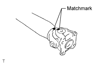
Place matchmarks on the flange yoke and sleeve yoke.
-
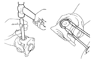
Using a brass bar and hammer, slightly tap in the spider bearing outer races.
-
Using 2 screwdrivers, remove the 4 snap rings from the grooves.
-
Clamp the propeller shaft in a vise between aluminum plates.
-
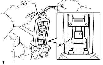
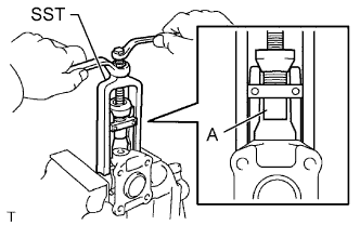
Using SST, push the sleeve yoke side spider bearing until: 1) the spider almost touches the sleeve yoke or propeller shaft, and 2) the spider bearing on the opposite side is partially pushed out.
- SST
- 09332-25010
Tech Tips
Before installing SST, sufficiently raise the part labeled A. If part A is too low, SST may be difficult to install.
-
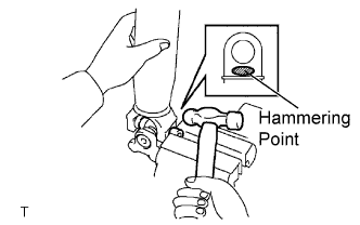
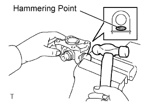
Clamp the pushed out spider bearing outer race in a vise and tap the propeller shaft to remove the spider bearing.
Note
Do not tap the shaft tube.
Tech Tips
Remove the spider bearing from the opposite side of the spider using the same procedure.
-
Separate the flange yoke and spider from the propeller shaft.
-
Reinstall the 2 removed spider bearings to the spider and clamp the spider bearings in a vise.
-
Using SST, push the flange yoke side spider bearing until: 1) the spider almost touches the flange yoke, and 2) the spider bearing on the opposite side is partially pushed out.
- SST
- 09332-25010
Tech Tips
Before installing SST, sufficiently raise the part labeled A. If part A is too low, SST may be difficult to install.
-
Clamp the pushed out spider bearing outer race in a vise and tap the flange yoke to remove the spider bearing.
Tech Tips
Remove the spider bearing from the opposite side of the spider using the same procedure.
-
Separate the spider from the flange yoke.
-