TRANSFER ASSEMBLY INSPECTION

-
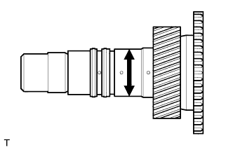
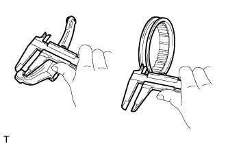
INSPECT TRANSFER INPUT SHAFT
-
Using a micrometer, measure the diameter of the input shaft journal surface.
Minimum diameter 47.59 mm (1.8736 in.) If the diameter is less than the minimum, replace the input shaft.
-
Using a caliper gauge, measure the inside diameter of the input shaft bushing.
Maximum inside diameter 48.14 mm (1.8953 in.) If the inside diameter is greater than the maximum, replace the input shaft.
-
-
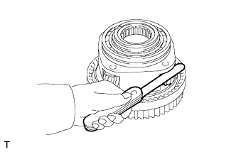
INSPECT PLANETARY PINION GEAR THRUST CLEARANCE
-
Using a feeler gauge, measure the thrust clearance of the pinion gear.
Standard clearance 0.11 to 0.84 mm (0.0043 to 0.0331 in.) Maximum clearance 0.84 mm (0.0331 in.) If the clearance is greater than the maximum, replace the planetary gear.
-
-
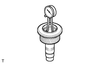
INSPECT PLANETARY PINION GEAR RADIAL CLEARANCE
-
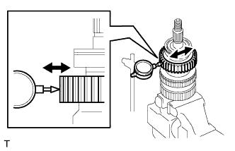
Using a dial indicator, measure the radial clearance of the pinion gear.
Standard clearance 0.009 to 0.038 mm (0.0004 to 0.0015 in.) Maximum clearance 0.038 mm (0.0015 in.) If the clearance is greater than the maximum, replace the planetary gear.
-
-
INSPECT TRANSFER DRIVE SPROCKET THRUST CLEARANCE
-
Using a feeler gauge, measure the thrust clearance of the drive sprocket.
Standard clearance 0.15 to 0.24 mm (0.0059 to 0.0094 in.) Maximum clearance 0.24 mm (0.0094 in.) If the clearance is greater than the maximum, replace the drive sprocket.
-
-
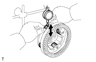
INSPECT TRANSFER DRIVE SPROCKET RADIAL CLEARANCE
-
Using a dial indicator, measure the radial clearance of the drive sprocket.
Standard clearance 0.01 to 0.06 mm (0.0004 to 0.0024 in.) Maximum clearance 0.06 mm (0.0024 in.) If the clearance is greater than the maximum, replace the drive sprocket, output shaft or needle roller bearing.
-
-
INSPECT REAR TRANSFER OUTPUT SHAFT
-
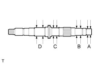
Using a micrometer, measure the diameter of the output shaft journal surface.
Standard diameter Position Specified Condition A 27.98 to 27.99 mm (1.1016 to 1.1020 in.) B 31.98 to 32.00 mm (1.2591 to 1.2598 in.) C 34.98 to 35.00 mm (1.3772 to 1.3780 in.) D 36.98 to 37.00 mm (1.4559 to 1.4567 in.) Minimum diameter Position Specified Condition A 27.98 mm (1.1016 in.) B 31.98 mm (1.2591 in.) C 34.98 mm (1.3772 in.) D 36.98 mm (1.4559 in.) If the diameter is less than the minimum, replace the output shaft.
-
-
INSPECT TRANSFER HIGH AND LOW CLUTCH SLEEVE AND NO. 2 TRANSFER GEAR SHIFT FORK CLEARANCE
-
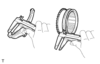
Using a vernier caliper, measure the thickness of the No. 2 gear shift fork claw.
Standard thickness 10 mm (0.3937 in.) -
Using a vernier caliper, measure the groove of the high and low clutch sleeve.
Standard distance 10.5 mm (0.4133 in.) -
Calculate the clearance between the high and low clutch sleeve and No. 2 gear shift fork.
Standard clearance 0.26 to 0.84 mm (0.0102 to 0.0331 in.) Maximum clearance 0.84 mm (0.0331 in.) If the clearance is greater than the maximum, replace the high and low clutch sleeve or No. 2 gear shift fork.
-
-
INSPECT FRONT DRIVE CLUTCH SLEEVE AND CENTER DIFFERENTIAL LOCK FORK CLEARANCE
-
Using a vernier caliper, measure the thickness of the center differential lock fork claw.
Standard thickness 10 mm (0.3937 in.) -
Using a vernier caliper, measure the groove of the front drive clutch sleeve.
Standard distance 10.5 mm (0.4133 in.) -
Calculate the clearance between the front drive clutch sleeve and center differential lock fork.
Standard clearance 0.26 to 0.84 mm (0.0102 to 0.0331 in.) Maximum clearance 0.84 mm (0.0331 in.) If the clearance is greater than the maximum, replace the front drive clutch sleeve or center differential lock fork.
-
-
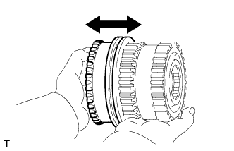
INSPECT CENTER DIFFERENTIAL CASE AND TRANSFER HIGH AND LOW CLUTCH SLEEVE
-
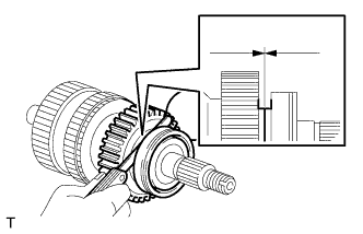
Check that the tip of the spline gear of the clutch sleeve is not worn.
-
Install the clutch sleeve to the differential case and check that the clutch sleeve moves smoothly.
If the results are not as specified, replace the differential case and clutch sleeve.
-
-
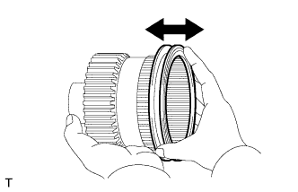
INSPECT CENTER DIFFERENTIAL CASE AND FRONT DRIVE CLUTCH SLEEVE
-
Check that the tip of the spline gear of the clutch sleeve is not worn.
-
Install the clutch sleeve to the differential case and check that the clutch sleeve moves smoothly.
If the results are not as specified, replace the differential case and clutch sleeve.
-