INPUT SHAFT REMOVAL

-
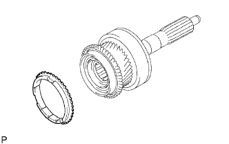
REMOVE NO. 2 SYNCHRONIZER RING
-
Remove the synchronizer ring from the input shaft.
-
-
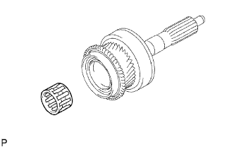
REMOVE INPUT SHAFT BEARING
-
Remove the bearing from the input shaft.
-
-
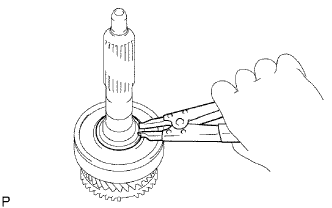
REMOVE FRONT BEARING SHAFT SNAP RING
-
Using a snap ring expander, remove the snap ring from the input shaft.
-
-
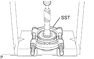
REMOVE INPUT SHAFT FRONT BEARING
-
Using SST and a press, press out the front bearing from the input shaft.
- SST
- 09950-00020
-
-
INSPECT NO. 2 SYNCHRONIZER RING
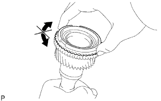
-
Apply gear oil to the cone of the input shaft, and check that it does not turn in both direction while pushing the No. 2 synchronizer ring.
If it can turn, replace the No. 1 synchronizer ring .
-
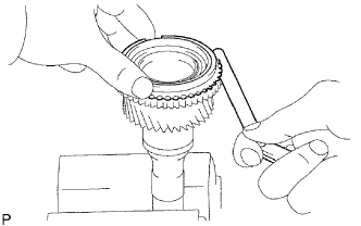
Push the No. 2 synchronizer ring to the cone of the input shaft. Measure the clearance between the No. 2 synchronizer ring and input shaft.
Standard clearance 0.70 to 1.70 mm (0.0276 to 0.0669 in.) If the clearance is not as specified, replace the synchronizer ring No. 2 with a new one.
-