MANUAL TRANSMISSION UNIT INSTALLATION

-
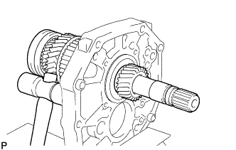
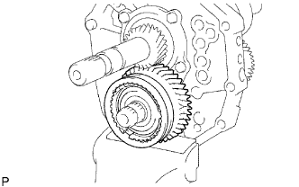
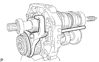
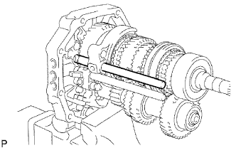
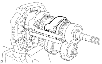
INSTALL OUTPUT SHAFT ASSEMBLY
-
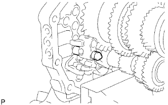
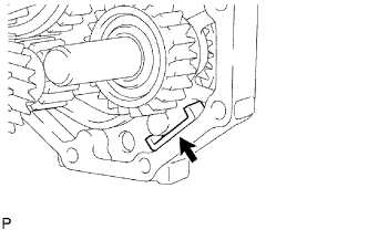
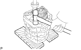
Apply gear oil to the sliding part of the output shaft.
-
Using a plastic-faced hammer, install the output shaft by tapping the intermediate plate.
-
-
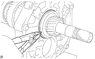
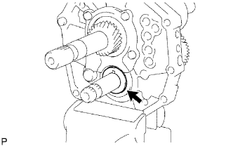
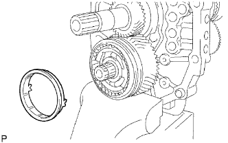
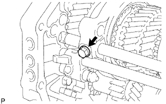
INSTALL OUTPUT SHAFT BEARING SHAFT SNAP RING
-
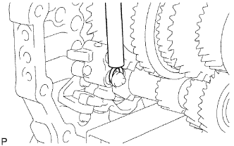
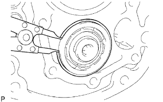
Using a snap ring expander, install the shaft snap ring to the output shaft.
-
-
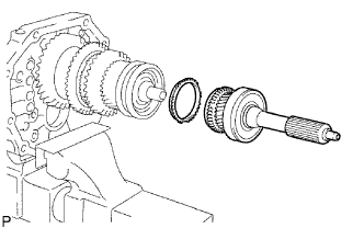
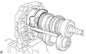
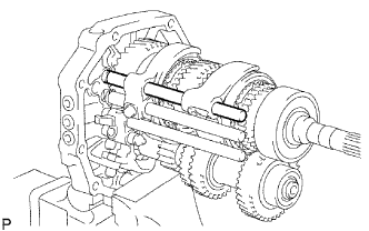
INSTALL INPUT SHAFT ASSEMBLY
-
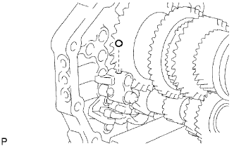
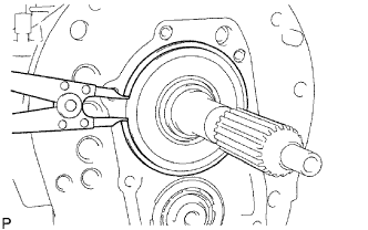
Apply gear oil to the input shaft and No. 2 synchronizer ring, and install them to the output shaft.
Note
-
Install the No. 2 synchronizer ring so that its groove fits into the No. 2 synchromesh shifting key.
-
Check that the input shaft rotates slightly.
-
-
-
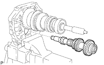
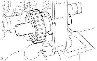
INSTALL COUNTER GEAR
-
Temporarily install the counter gear to the intermediate plate.
-
-
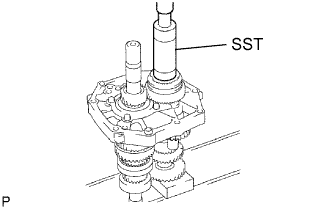
INSTALL COUNTER SHAFT CENTER BEARING
-
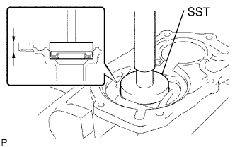
Using SST and a hammer, tap in a new center bearing to the intermediate plate.
- SST
- 09316-60011
Tech Tips
Install the bearing while tapping the tip of the counter gear with a plastic-faced hammer so that the counter gear will not hit the side wall of the output shaft gear by being pushed forward.
-
-
INSTALL REVERSE IDLER GEAR
-
Apply gear oil to each sliding part of the reverse idler gear and the reverse idler gear shaft, and install the reverse idler gear and the reverse idler shaft to the intermediate plate.
Note
Face the groove side of the reverse idler shaft to the rear side, and install it from the rear side.
-
-
INSTALL REAR BEARING RETAINER
-
Insert the protrusion of the bearing retainer into the groove of the reverse idler gear shaft. Then install the bearing retainer with the 4 bolts.
- Torque:
- 18 N*m { 185 kgf*cm, 13 ft.*lbf }
-
-
INSTALL 5TH GEAR THRUST WASHER PIN
-
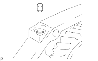
Apply MP grease to the washer pin, and install it to the counter gear.
-
-
INSTALL 5TH GEAR THRUST WASHER
-
Apply gear oil to the thrust washer, and install it to the counter gear.
Note
Install the thrust washer so that its chamfer side faces to the front side.
-
-
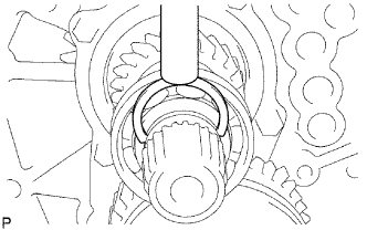
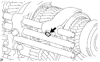
INSTALL NO. 3 SYNCHROMESH SHIFTING KEY SPRING
-
Apply gear oil to the sliding part of the No. 3 transmission hub sleeve, and install it to the counter 5th gear.
Note
Be sure of the direction of the No. 3 transmission hub sleeve and the counter 5th gear.
-
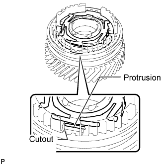
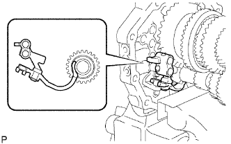
Install the 2 No. 3 synchromesh shifting keys and No. 3 synchromesh shifting key spring to the counter 5th gear as shown in the illustration.
Tech Tips
When installing the No. 3 synchromesh shifting key spring, make sure the protrusion fits into the cutout.
-
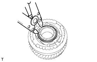
Using a snap ring expander, install the snap ring to the counter 5th gear.
-
-
INSTALL COUNTER 5TH GEAR BEARING
-
Apply gear oil to the bearing and install it to the counter 5th gear.
-
-
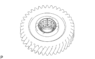
INSTALL COUNTER 5TH GEAR
-
Apply gear oil to the 5th gear and No. 3 transmission hub sleeve, and install it to the counter gear.
-
-
INSTALL NO. 3 SYNCHRONIZER RING
-
Apply gear oil to the No. 3 synchronizer ring, and install it to the counter gear.
Note
Install the No. 3 synchronizer ring so that its groove fits into the No. 3 synchromesh shifting key.
-
-
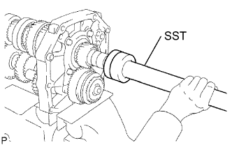
INSTALL NO. 5 GEAR SPLINE PIECE
-
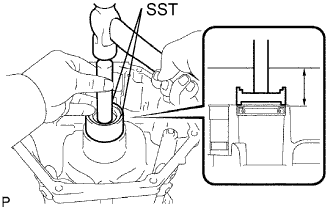
Using SST and a press, press in the gear spline piece to the counter gear.
- SST
- 09316-60011 ( 09316-00011 )
Note
Check that the gear rotate freely.
-
-
INSTALL COUNTER GEAR REAR SHAFT SNAP RING
-
Select the snap ring so that the thrust gap between the No. 5 gear spline piece and snap ring to be within the specification.
Standard clearance 0.10 mm (0.0039 in.) or less Standard snap ring thickness Thickness 2.80 to 2.85 mm (0.1102 to 0.1122 in.) 2.85 to 2.90 mm (0.1122 to 0.1141 in.) 2.90 to 2.95 mm (0.1141 to 0.1160 in.) 2.95 to 3.00 mm (0.1160 to 0.1181 in.) 3.00 to 3.05 mm (0.1181 to 0.1200 in.) 3.05 to 3.10 mm (0.1200 to 0.1220 in.) 3.10 to 3.15 mm (0.1220 to 0.1240 in.) -
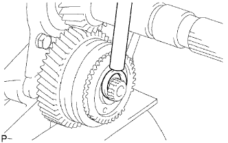
Using a brass bar and hammer, tap in the snap ring.
-
-
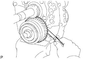
INSPECT COUNTER 5TH GEAR THRUST CLEARANCE
-
Using a feeler gauge, measure the thrust clearance.
Standard clearance 0.10 to 0.35 mm (0.0039 to 0.0138 in.) If the clearance is not as specified, replace the counter shaft 5th gear and No. 3 synchronizer ring.
-
-
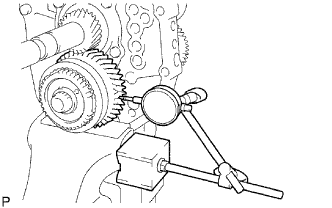
INSPECT COUNTER 5TH GEAR RADIAL CLEARANCE
-
Using a dial indicator, check the gear radial clearance.
Standard clearance 0.015 to 0.068 mm (0.0006 to 0.0027 in.) If the clearance is not as specified, replace the counter 5th gear bearing.
-
-
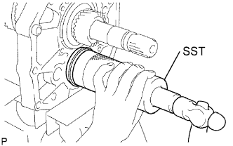
INSTALL OUTPUT SHAFT REAR BEARING
-
Using SST and a press, press in the spacer and a new rear bearing to the output shaft.
- SST
- 09309-35010
-
-
INSTALL OUTPUT SHAFT BEARING SHAFT SNAP RING
-
Select a shaft snap ring so that the thrust gap between the output shaft bearing shaft and snap ring to be within the specification.
Standard clearance 0.10 mm (0.0039 in.) or less Standard snap ring thickness Thickness Thickness 2.65 to 2.70 mm (0.1043 to 0.1063 in.) 3.10 to 3.15 mm (0.1220 to 0.1240 in.) 2.70 to 2.75 mm (0.1063 to 0.1083 in.) 3.15 to 3.20 mm (0.1240 to 0.1260 in.) 2.75 to 2.80 mm (0.1083 to 0.1102 in.) 3.20 to 3.25 mm (0.1260 to 0.1280 in.) 2.80 to 2.85 mm (0.1102 to 0.1122 in.) 3.25 to 3.30 mm (0.1280 to 0.1299 in.) 2.85 to 2.90 mm (0.1122 to 0.1141 in.) 3.30 to 3.35 mm (0.1299 to 0.1319 in.) 2.90 to 2.95 mm (0.1141 to 0.1160 in.) 3.35 to 3.40 mm (0.1319 to 0.1339 in.) 2.95 to 3.00 mm (0.1160 to 0.1181 in.) 3.40 to 3.45 mm (0.1339 to 0.1358 in.) 3.00 to 3.05 mm (0.1181 to 0.1200 in.) 3.45 to 3.50 mm (0.1358 to 0.1378 in.) 3.05 to 3.10 mm (0.1200 to 0.1220 in.) - -
Using a brass bar and hammer, tap in the snap ring.
-
-
INSTALL REVERSE SHIFT ARM BRACKET
-
Install the arm bracket on the intermediate plate with the 2 bolts.
- Torque:
- 18 N*m { 185 kgf*cm, 13 ft.*lbf }
-
-
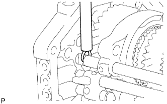
INSTALL REVERSE SHIFT FORK
-
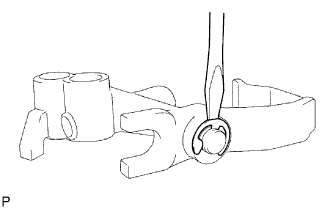
Install the shift arm to the shift fork. Using a screwdriver and hammer, tap in a new E-ring.
-
Install the tip of the reverse shift arm to the reverse idler gear. Align the cut end of the reverse shift arm with the reverse shift arm bracket pin, and install them.
-
-
INSTALL NO. 4 SHIFT FORK SHAFT
-
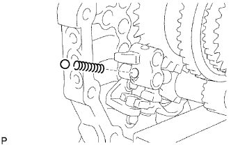
Install the compression spring and reverse shift fork ball to the reverse shift fork.
-
Apply gear oil to the sliding part of the No. 4 shift fork shaft.
-
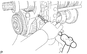
Using a screwdriver, install the No. 3 shift fork shaft by pushing the reverse shift fork ball lightly.
-
Using a brass bar and hammer, tap in the snap ring to the No. 4 shift fork shaft.
-
-
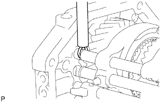
INSTALL NO. 3 SHIFT FORK SHAFT
-
Install the reverse shift fork ball to the reverse shift fork.
-
Install the No. 1 shift interlock roller to the intermediate plate.
-
Install the No. 3 shift fork to the No. 3 transmission hub sleeve and No. 3 shift fork shaft to the intermediate plate from the front side.
-
Using a brass bar and hammer, tap in the snap ring to the shift fork shaft.
-
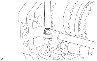
Using a 5 mm pin punch and hammer, tap in the slotted spring pin to the No. 3 shift fork.
-
-
INSTALL NO. 1 SHIFT FORK SHAFT
-

Install the No. 1 shift interlock roller to the intermediate plate.
-
Install the No. 1 shift fork to the reverse gear.
-
Install the No. 1 shift fork shaft to the intermediate plate from the rear side.
-
Install the shift fork set bolt to the No. 1 shift fork.
- Torque:
- 20 N*m { 204 kgf*cm, 14 ft.*lbf }
-
Using a brass bar and hammer, tap in the shift fork shaft snap ring to the No. 1 shift fork shaft.
-
-
INSTALL NO. 2 SHIFT SHAFT
-
Install the shift interlock pin and No. 1 shift interlock roller to the intermediate plate.
-
Install the No. 2 shift fork to the No. 2 transmission hub sleeve.
-
Apply gear oil to the No. 2 shift fork, and install it to the intermediate plate from the rear side.
-
Install the shift fork set bolt to the No. 2 shift fork.
- Torque:
- 20 N*m { 204 kgf*cm, 14 ft.*lbf }
-
Using a brass bar and hammer, tap in the snap ring to the No. 2 shift fork shaft.
-
-
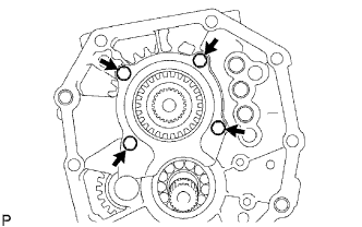
INSTALL NO. 1 SHIFT DETENT BALL SPRING SEAT
-
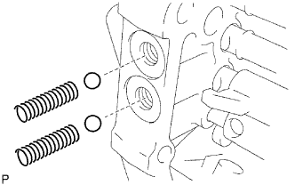
Install the 2 compression springs and 2 shifts detent balls to the intermediate plate.
-
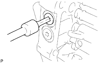
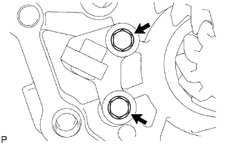
Using a T40 ''torx'' socket wrench, install the 3 spring seats to the intermediate plate.
- Torque:
- 18.5 N*m { 190 kgf*cm, 14 ft.*lbf }
-
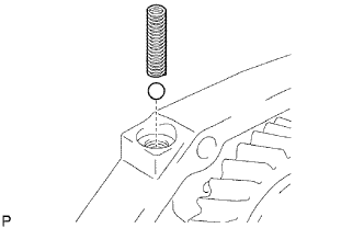
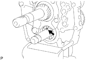
Install the detent ball and low side compression spring to the intermediate plate.
-
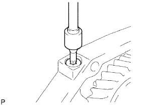
Using a T40 ''torx'' socket wrench, install the spring seat to the intermediate plate.
- Torque:
- 18.5 N*m { 190 kgf*cm, 14 ft.*lbf }
-
-
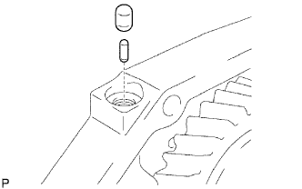
INSTALL TRANSMISSION MAGNET

-
Clean the transmission magnet, and install it to the intermediate plate.
-
-
INSTALL MANUAL TRANSMISSION CASE
-
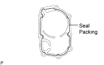
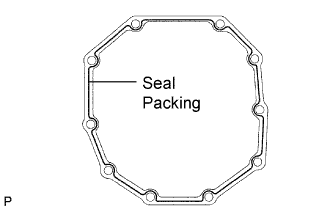
Apply seal packing to the manual transmission case as shown in the illustration.
Seal packing Toyota Genuine Seal Packing 1281, Three Bond 1281 or equivalent -
Using a plastic-faced hammer, tap the transmission case to attach it to the intermediate plate.
-
-
INSTALL NO. 1 COUNTER GEAR FRONT BEARING SNAP RING
-
Using a snap ring expander, install the snap ring to the transmission case.
-
-
INSTALL FRONT BEARING SHAFT SNAP RING
-
Using a snap ring expander, install the snap ring to the transmission case.
-
-
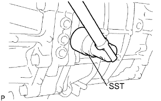
INSTALL TRANSMISSION FRONT BEARING RETAINER OIL SEAL
-
Using SST and a hammer, tap in a new oil seal to the front bearing retainer.
- SST
- 09950-60010 ( 09951-00300, 09951-00520, 09952-06010 )
- 09950-70010 ( 09951-07100 )
Standard oil seal depth 11.20 to 12.20 mm (0.4409 to 0.4803 in.) -
Lightly apply MP grease to the tip of the oil seal.
-
-
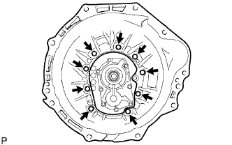
INSTALL FRONT BEARING RETAINER
-
Apply seal packing to the bearing retainer as shown in the illustration.
Seal packing Toyota Genuine Seal Packing 1281, Three Bond 1281 or equivalent -
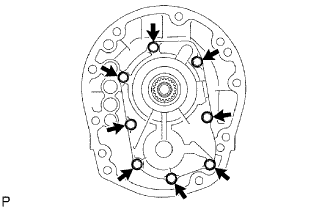
Install the front bearing retainer to the transmission case with the 8 bolts.
- Torque:
- 16.5 N*m { 170 kgf*cm, 12 ft.*lbf }
-
Check that the input shaft and output shaft rotate smoothly.
-
-
INSTALL TRANSFER ADAPTER OIL SEAL
-
Using SST and a hammer, tap in a new oil seal to the transfer adapter.
- SST
- 09710-30050
- 09950-70010 ( 09951-07100 )
Standard oil seal depth 45.4 to 46.4 mm (1.787 to 1.827 in.) -
Lightly apply MP grease to the tip of the oil seal.
-
-
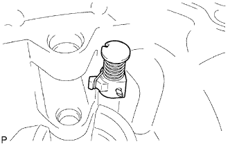
INSTALL REVERSE RESTRICT PIN
-
Install the restrict pin to the transfer adapter.
-
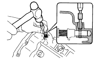
Using a 5 mm pin punch and hammer, tap in the slotted pin to the transfer adapter.
-
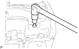
Using a T40 ''torx'' socket wrench, install the reverse restrict pin plug to the transfer adapter.
-
-
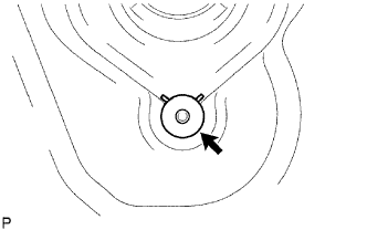
INSTALL OIL RECEIVER PIPE
-
Install the oil receiver pipe to the transfer adapter.
-
-
INSTALL TRANSFER ADAPTER
-
Apply seal packing to the transfer adapter as shown in the illustration.
Seal packing Toyota Genuine Seal Packing 1281, Three Bond 1281 or equivalent -
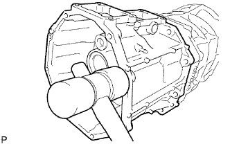
Using a plastic-faced hammer, tap the transfer adapter to attach it to the transmission case.
-
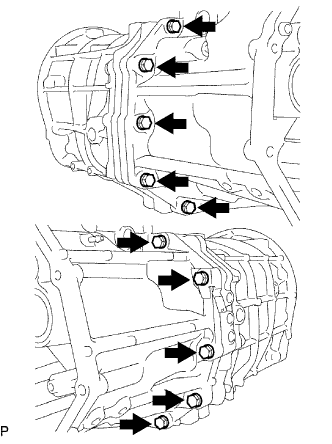
Install the transfer adapter to the transmission case with the 10 bolts.
- Torque:
- 37 N*m { 377 kgf*cm, 27 ft.*lbf }
-
-
INSTALL SHIFT AND SELECT LEVER SHAFT
-
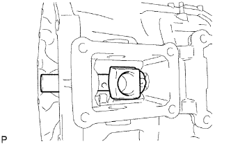
Install the shift and select lever shaft and shift lever housing to the transfer adapter.
-
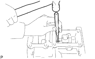
Using a 5 mm pin punch and hammer, tap in the slotted spring pin to the transfer adapter.
-
-
INSTALL TRANSFER CONTROL SHIFT LEVER RETAINER
-
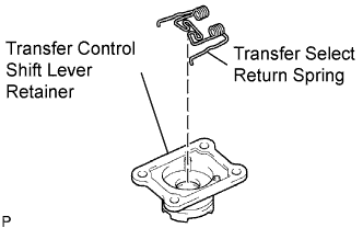
Install the select return spring on the shift lever retainer.
-
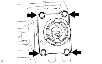
Install the shift lever retainer to the transfer adapter with the 4 bolts.
- Torque:
- 18 N*m { 185 kgf*cm, 13 ft.*lbf }
-
-
INSTALL CONTROL SHIFT LEVER RETAINER
-
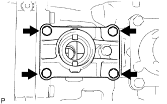
Install the control shift lever retainer and oil deflector.
-
Install the 4 bolts.
- Torque:
- 18 N*m { 185 kgf*cm, 13 ft.*lbf }
-
-
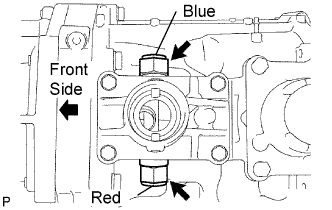
INSTALL RESTRICT PIN
-
Install the 2 restrict pins.
- Torque:
- 37 N*m { 377 kgf*cm, 27 ft.*lbf }
-
-
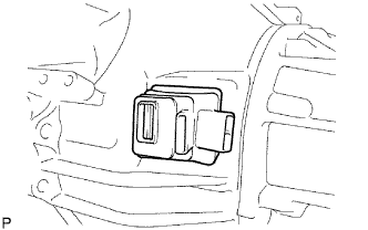
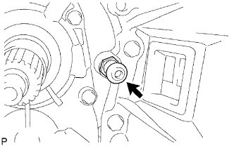
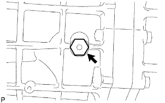
INSTALL BACK-UP LIGHT SWITCH ASSEMBLY
-
Using SST, install a new gasket and the back-up light switch to the transmission case.
- SST
- 09817-16011
- Torque:
- 44 N*m { 449 kgf*cm, 32 ft.*lbf }
-
-
INSTALL CLUTCH HOUSING
-
Install the clutch housing to the transmission case with the 9 bolts.
- Torque:
- 36 N*m { 370 kgf*cm, 27 ft.*lbf }
-
-
INSTALL CLUTCH RELEASE FORK BOOT
-
Install the fork boot to the clutch housing.
-
-
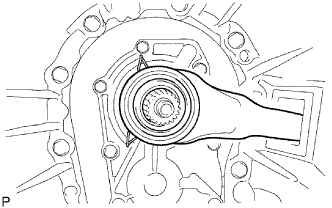
INSTALL RELEASE FORK SUPPORT
-
Install the release fork support to the clutch housing.
- Torque:
- 47 N*m { 480 kgf*cm, 35 ft.*lbf }
-
-
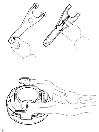
INSTALL CLUTCH RELEASE BEARING ASSEMBLY
-
Apply Multemp 8158 Grease or equivalent to the clutch release bearing, and install it to the clutch release fork.
Grease Multemp 8158 Grease or equivalent
-
-
INSTALL CLUTCH RELEASE FORK SUB-ASSEMBLY
-
Install the clutch release fork.
-
Apply the clutch spline grease to the spline of the input shaft.
-
-
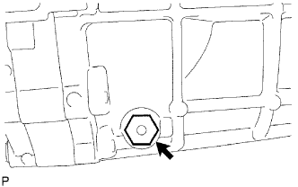
INSTALL DRAIN PLUG
-
Install a new gasket and the drain plug to the transmission case.
- Torque:
- 37 N*m { 377 kgf*cm, 27 ft.*lbf }
-
-
INSTALL FILLER PLUG
-
Install a new gasket and the filler plug to the transmission case.
- Torque:
- 37 N*m { 377 kgf*cm, 27 ft.*lbf }
-