MANUAL TRANSMISSION ASSEMBLY INSTALLATION

-
INSTALL TRANSFER ASSEMBLY
-
Install the transfer Click here.
-
-
INSTALL MANUAL TRANSMISSION UNIT ASSEMBLY
-
Align the input shaft with the clutch disc and install the transmission to the engine.
-
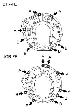
2TR-FE:
Install the 7 bolts.
- Torque:
- 72 N*m { 730 kgf*cm, 53 ft.*lbf, for bolt A }
- 37 N*m { 377 kgf*cm, 27 ft.*lbf, for bolt B }
-
1GR-FE:
Install the 9 bolts.
- Torque:
- 72 N*m { 730 kgf*cm, 53 ft.*lbf, for bolt A }
- 37 N*m { 377 kgf*cm, 27 ft.*lbf, for bolt B }
-
-
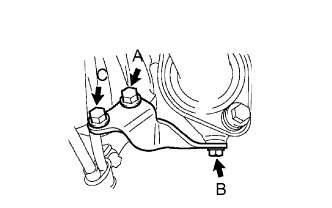
INSTALL EXHAUST MANIFOLD STAY (for 2TR-FE)
-
Install the exhaust manifold stay with the 3 bolts.
- Torque:
- 44 N*m { 449 kgf*cm, 32 ft.*lbf, for bolt A }
- 30 N*m { 306 kgf*cm, 22 ft.*lbf, for bolt B }
- 72 N*m { 730 kgf*cm, 53 ft.*lbf, for bolt C }
-
-
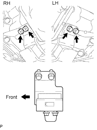
INSTALL REAR NO. 1 ENGINE MOUNTING INSULATOR
-
Install the mounting insulator with the 4 bolts.
- Torque:
- 44 N*m { 449 kgf*cm, 32 ft.*lbf }
-
-
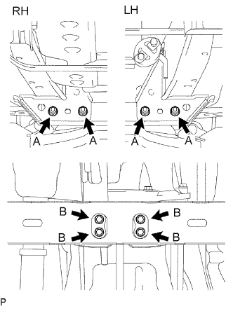
INSTALL NO. 3 FRAME CROSSMEMBER SUB-ASSEMBLY
-
Install the frame crossmember with the 4 bolts and 4 nuts.
- Torque:
- 50 N*m { 510 kgf*cm, 37 ft.*lbf, for bolt A }
-
Install the 4 set bolts to the No. 1 engine mounting insulator rear.
- Torque:
- 27 N*m { 275 kgf*cm, 20 ft.*lbf, for bolt B }
-
-
INSTALL STARTER ASSEMBLY
for 2TR-FE: Click here
for 1GR-FE: Click here
-
CONNECT CLUTCH RELEASE CYLINDER ASSEMBLY (for 2TR-FE)
-
Install the release cylinder with the 2 bolts.
- Torque:
- 12 N*m { 120 kgf*cm, 9 ft.*lbf }
-
-
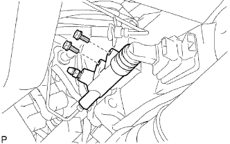
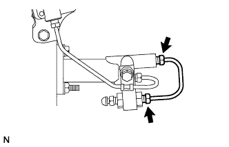
INSTALL CLUTCH RELEASE CYLINDER ASSEMBLY (for 1GR-FE)
-
Install the accumulator with the 3 bolts.
- Torque:
- 12 N*m { 120 kgf*cm, 9 ft.*lbf }
-
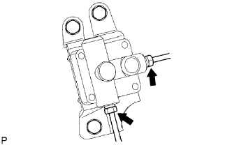
Using union nut wrench connect the 2 flexible hose tubes.
- Torque:
- 15.5 N*m { 158 kgf*cm, 11 ft.*lbf }
Note
Use the formula to calculate special torque value for situations where a union nut wrench is combined with a torque wrench Click here.
-
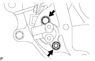
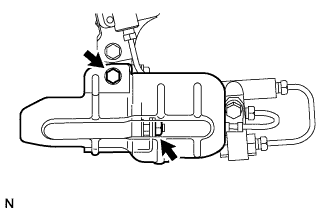
Install the clutch release cylinder with the 2 bolts.
- Torque:
- 12 N*m { 120 kgf*cm, 9 ft.*lbf }
-
Using union nut wrench, connect the flexible tube.
- Torque:
- 15.5 N*m { 158 kgf*cm, 11 ft.*lbf }
Note
Use the formula to calculate special torque value for situations where a union nut wrench is combined with a torque wrench Click here.
-
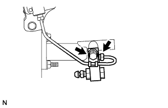
Install the 2 way with the bolt.
- Torque:
- 19 N*m { 194 kgf*cm, 14 ft.*lbf }
-
Using union nut wrench, install the flexible tube.
- Torque:
- 15.5 N*m { 158 kgf*cm, 11 ft.*lbf }
Note
Use the formula to calculate special torque value for situations where a union nut wrench is combined with a torque wrench Click here.
-
Install the release cylinder heat insulator with the bolt and the nut.
- Torque:
- 12 N*m { 120 kgf*cm, 9 ft.*lbf }
-
-
CONNECT WIRE HARNESS
-
Transmission side:
Connect the back-up light switch connector.
-
Transfer side:
Connect the No. 1, No. 2 and No. 3 transfer indicator switch connectors, and vehicle speed sensor connector.
-
-
INSTALL FRONT EXHAUST PIPE ASSEMBLY
for 2TR-FE: Click here
for 1GR-FE: Click here
-
INSTALL REAR PROPELLER SHAFT ASSEMBLY
-
INSTALL FRONT PROPELLER SHAFT ASSEMBLY
-
ADD MANUAL TRANSMISSION OIL
Oil grade GL-4 or GL-5 Viscosity SAE 75W-90 Standard capacity 2.2 liters (2.3 US qts, 1.9 Imp. qts) - Torque:
- 37 N*m { 377 kgf*cm, 27 ft.*lbf }
-
INSTALL TRANSFER CASE LOWER PROTECTOR
-
Install the transfer case lower protector with the 4 bolts.
- Torque:
- 18 N*m { 183 kgf*cm, 13 ft.*lbf }
-
-
INSTALL TRANSFER HIGH AND LOW SHIFT LEVER ASSEMBLY
-
Install the transfer shift lever.
Tech Tips
Apply MP grease to the tip of the transfer shift lever.
-
Using pliers, install the snap ring.
-
-
INSTALL FLOOR SHIFT SHIFT LEVER ASSEMBLY
-
Cover the shift lever cap with a cloth.
-
Press down on the shift lever cap and rotate it clockwise to install it.
Tech Tips
Apply MP grease to the tip of the shift lever.
-
-
INSTALL SHIFT LEVER BOOT ASSEMBLY
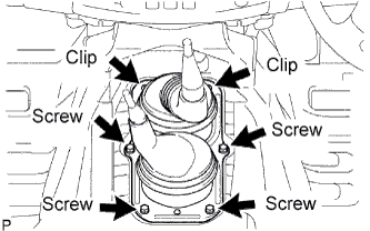
-
Install the shift lever boot with the 4 screws and 2 clips.
-
-
INSTALL CONSOLE BOX ASSEMBLY
-
CONNECT CABLE TO NEGATIVE BATTERY TERMINAL
-
PERFORM INITIALIZATION
-
Perform initialization Click here.
Note
Certain systems need to be initialized after disconnecting and reconnecting the cable from the negative (-) battery terminal.
-
-
BLEED AIR FROM CLUTCH PIPE LINE (for 1GR-FE)
-
Remove the brake master cylinder reservoir filler cap assembly.
-
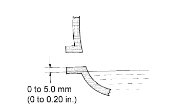
Add brake fluid to keep the level between the MIN and MAX lines of the reservoir while bleeding the clutch line.
Fluid SAE J1703 or FMVSS No. 116 DOT3 -
Remove the bleeder plug cap.
-
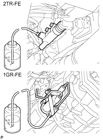
Connect a vinyl tube to the bleeder plug.
-
Depress the clutch pedal several times, and then loosen the bleeder plug with the pedal depressed.
-
At the point when fluid stops coming out, tighten the bleeder plug, and then release the clutch pedal.
-
Repeat the previous 2 steps until all the air in the fluid is completely bled out.
-
Tighten the bleeder plug.
- Torque:
- 11 N*m { 110 kgf*cm, 8 ft.*lbf }
-
Install the bleeder plug cap.
-
Check that all the air has been bled out of the clutch line.
-
Check for brake fluid leaks.
-
Check the brake fluid level in the reservoir Click here.
-
Install the brake master cylinder reservoir filler cap assembly.
-
-
CHECK FOR CLUTCH FLUID LEAKAGE
-
INSPECT AND ADJUST CLUTCH PEDAL ASSEMBLY (for 1GR-FE)
-
CHECK FLUID LEVEL IN RESERVOIR (for 1GR-FE)
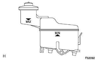
-
Check the fluid level and add fluid if necessary.
Fluid SAE J1703 or FMVSS No. 116 DOT3 Tech Tips
Add fluid to a level between the reservoir's MIN and MAX lines.
-
-
INSTALL NO. 3 ENGINE UNDER COVER
- Torque:
- 28 N*m { 286 kgf*cm, 21 ft.*lbf }
-
INSTALL NO. 2 ENGINE UNDER COVER
- Torque:
- 28 N*m { 286 kgf*cm, 21 ft.*lbf }
-
INSTALL NO. 1 ENGINE UNDER COVER
- Torque:
- 28 N*m { 286 kgf*cm, 21 ft.*lbf }