CLUTCH PEDAL INSTALLATION

-
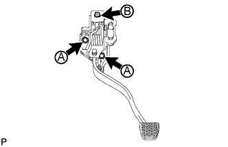
INSTALL CLUTCH PEDAL ASSEMBLY
-
Install the clutch pedal with the bolt and 2 nuts.
- Torque:
- for nut A
- 14 N*m { 145 kgf*cm, 10 ft.*lbf }
- for bolt B
- 18 N*m { 184 kgf*cm, 13 ft.*lbf }
-
w/ Clutch Switch:
Connect the clutch switch connector.
-
-
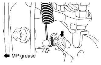
INSTALL CLUTCH MASTER CYLINDER PUSH ROD CLEVIS
-
Apply MP grease to the contact surface of the clevis pin.
-
Connect the clutch master cylinder push rod clevis with the clevis pin and install a new clip.
-
w/o Turn Over:
Connect the clutch pedal spring to the clevis pin and clutch pedal support to install it.
-
-
INSPECT AND ADJUST CLUTCH PEDAL ASSEMBLY
-
Lift up the floor carpet to expose the asphalt sheet under the pedal.
-
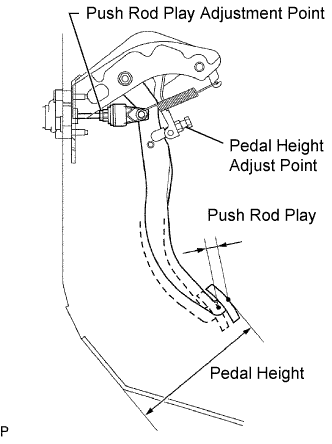
Check that the pedal height is correct.
Pedal height from dash panel 179.9 to 189.9 mm (7.08 to 7.48 in.) -
w/o Clutch Switch:
Adjust the pedal height.
-
Loosen the lock nut and turn the stopper bolt until the pedal height is within the specified range.
-
Tighten the lock nut.
- Torque:
- 25 N*m { 255 kgf*cm, 18 ft.*lbf }
-
-
w/ Clutch Switch:
Adjust the pedal height.
-
Loosen the lock nut of stopper bolt and clutch switch. Then turn clutch switch backward.
-
Turn the stopper bolt until the pedal height is within the specified range.
-
Tighten the lock nut of stopper bolt.
- Torque:
- 25 N*m { 255 kgf*cm, 18 ft.*lbf }
-
Adjust the clutch switch assembly Click here.
-
-
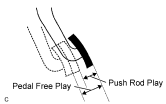
Check the pedal free play and push rod play.
Tech Tips
Pay close attention to the change in resistance to distinguish between pedal free play and push rod play while performing the inspection.
-
Depress the clutch pedal until resistance is felt.
-
Measure the distance between the pedal's released position and the position in the previous step.
Standard pedal free play 5.0 to 15.0 mm (0.197 to 0.591 in.) -
Release the pedal. Using your finger, gently press the pedal until resistance increases slightly.
-
Measure the distance between the pedal's released position and the position in the previous step.
Standard push rod play at pedal top 1.0 to 5.0 mm (0.0394 to 0.197 in.)
-
-
Adjust the pedal free play and push rod play.
Tech Tips
The push rod play can be adjusted by changing the length of the push rod. Pedal free play changes together with push rod play.
-
Loosen the lock nut and turn the push rod until the pedal free play and push rod play are within the specified ranges.
Note
If pedal free play and push rod play are not within the standard range even after adjustment, inspect the related parts.
-
Tighten the lock nut.
- Torque:
- 12 N*m { 120 kgf*cm, 9 ft.*lbf }
-
After adjusting the pedal free play and push rod play, check the pedal height.
-
-
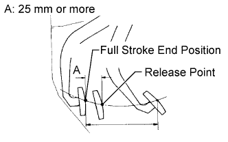
Check the clutch release point.
-
Pull the parking brake lever and use wheel chocks to stabilize the vehicle.
-
Start the engine and run it at idle.
-
Without depressing the clutch pedal, slowly move the shift lever to R until the gears contact.
-
Gently depress the clutch pedal and measure the stroke distance from the point that the gear noise stops (release point) up to the full stroke end position.
Standard distance A 25 mm (0.984 in.) or more If the distance is not as specified, perform the following operations.
-
Check pedal height.
-
Check push rod play and pedal free play.
-
Bleed air from clutch line.
-
Check clutch cover and disc.
-
-
-
-
ADJUST CLUTCH SWITCH ASSEMBLY
-
Loosen the adjusting nut.
-
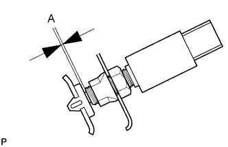
Adjust the switch position so that the clearance labeled A in the illustration, between the clutch switch and cushion, is within the specified range. Then, tighten the adjusting nut.
Standard Clearance A 0.6 to 1.0 mm (0.0236 to 0.0394 in.) - Torque:
- 16 N*m { 160 kgf*cm, 12 ft.*lbf }
Note
Before performing the clutch switch assembly adjustment, adjust the pedal free play Click here.
-
-
INSTALL COMBINATION METER ASSEMBLY
-
INSTALL LOWER INSTRUMENT PANEL FINISH PANEL SUB-ASSEMBLY
-
Attach the 3 guides, 2 claws and 3 clips to install the lower instrument panel finish panel.
-
-
CHECK FLUID LEVEL IN RESERVOIR