CLUTCH DRUM AND INPUT SHAFT ASSEMBLY REASSEMBLY

-
INSTALL DIRECT CLUTCH PISTON SUB-ASSEMBLY
-
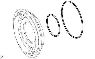
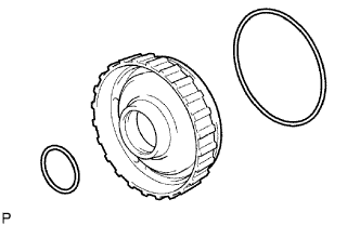
Coat 2 new O-rings with ATF, and install them in the direct clutch piston.
-
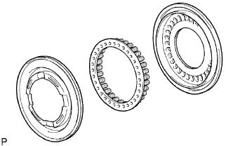
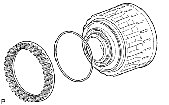
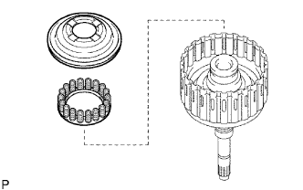
Install the No. 2 clutch balancer and direct clutch return spring to the direct clutch piston sub-assembly.
-
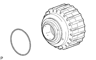
Coat a new O-ring with ATF, and install it on the clutch drum sub-assembly.
-
Be careful not to damage the O-rings. Press in the direct clutch piston into the clutch drum with both hands.
-
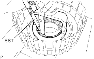
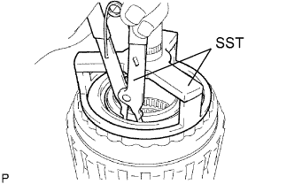
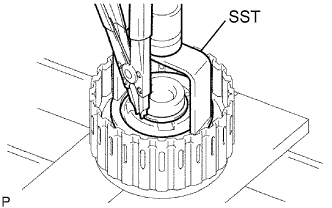
Place SST on the direct clutch piston, and compress the return spring with a press.
- SST
- 09320-89010
- 09350-30020 ( 09350-07070 )
Note
Stop pressing when the spring sheet is lowered to the place 1 to 2 mm (0.039 to 0.078 in.) from the snap ring groove to prevent the spring sheet from being deformed.
-
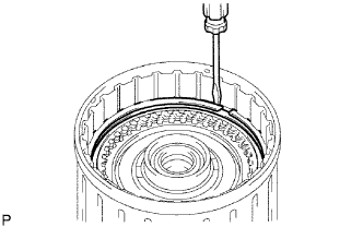
Install the snap ring with a snap ring expander.
Note
Do not expand the snap ring excessively.
-
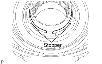
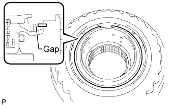
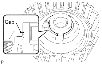
Set the end gap of the snap ring in the piston as shown in the illustration.
Note
Be sure the end gap of the snap ring is not aligned with the spring retainer claw.
-
-
INSTALL REVERSE CLUTCH PISTON SUB-ASSEMBLY
-
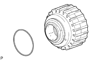
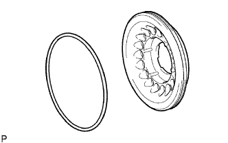
Coat a new O-ring with ATF, and install it on the clutch drum sub-assembly.
-
Coat a new O-ring with ATF, and install it on the reverse clutch piston sub-assembly.
-
Be careful not to damage the O-ring. Press in the clutch drum sub-assembly into the reverse clutch piston with both hands.
-
-
INSTALL REVERSE CLUTCH RETURN SPRING SUB-ASSEMBLY
-
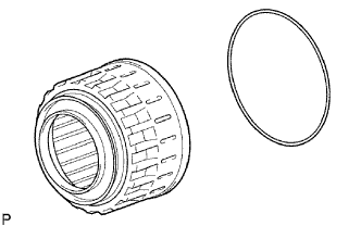
Coat a new O-ring with ATF, and install it on the reverse clutch piston sub-assembly.
-
Install the reverse clutch return spring onto the reverse clutch piston sub-assembly.
-
-
INSTALL NO. 3 CLUTCH BALANCER
-
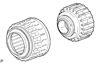
Place SST on the No. 3 clutch balancer, and compress the clutch balancer with a press.
- SST
- 09387-00070
- 09350-30020 ( 09350-07070 )
Note
Stop pressing when the spring sheet is lowered to the place 1 to 2 mm (0.039 to 0.078 in.) from the snap ring groove to prevent the spring sheet from being deformed.
-
Install the snap ring with a snap ring expander.
Note
Do not expand the snap ring excessively.
-
Set the end gap of the snap ring in the piston as shown in the illustration.
Note
Be sure the end gap of the snap ring is not aligned with the spring retainer claw.
-
-
INSTALL DIRECT CLUTCH DISC
-
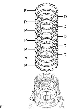
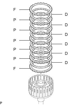
Install the 6 plates, 5 discs and reverse clutch flange on the clutch drum sub-assembly.
Install in order P - P - D - P - D - P - D - P - D - P - D - F Tech Tips
P = Plate
D = Disc
F = Flange
-
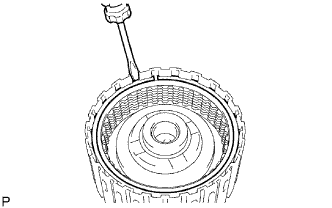
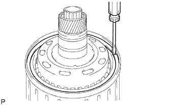
Using a screwdriver, install the 2 hole snap rings on the clutch drum sub-assembly.
-
-
INSPECT PACK CLEARANCE OF DIRECT CLUTCH
-
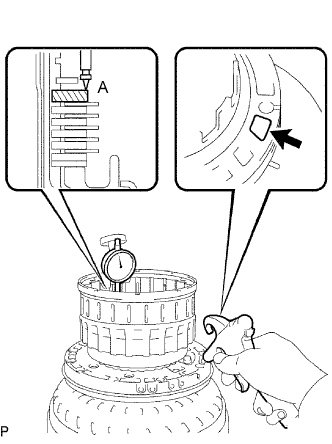
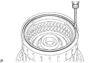
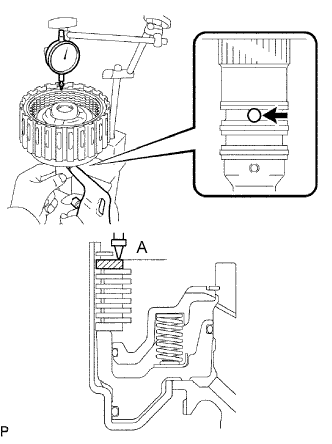
Using a dial gauge, measure the moving distance (distance A) of the clutch flange at both ends across a diameter while blowing air from the oil hole as shown in the illustration, and calculate the average.
Standard pack clearance 0.5 to 0.8 mm (0.020 to 0.031 in.) Note
Install a standard flange (3.4 mm (0.134 in.)) when measuring the moving distance (shaded area in the illustration).
Tech Tips
Flange moving distance A = 0.26 to 1.14 mm (0.010 to 0.045 in.)
Pack clearance = Flange moving distance A - 0.05 mm (0.002 in.)
-
If the pack clearance is not within the standard, select and install a clutch flange that makes the pack clearance within the standard.
Standard flange thickness No. Thickness No. Thickness 0 3.0 mm (0.118 in.) 5 3.5 mm (0.138 in.) 1 3.1 mm (0.122 in.) 6 3.6 mm (0.142 in.) 2 3.2 mm (0.126 in.) 7 3.7 mm (0.146 in.) 3 3.3 mm (0.130 in.) 8 3.8 mm (0.150 in.) 4 3.4 mm (0.134 in.) - -
-
-
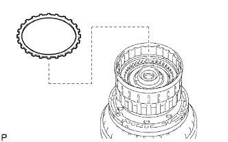
INSTALL REVERSE CLUTCH FLANGE
-
Install the reverse clutch flange to the clutch drum sub-assembly.
-
-
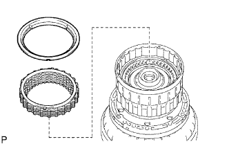
INSTALL REVERSE CLUTCH REACTION SLEEVE
-
Install the reverse clutch reaction sleeve, clutch cushion plate, reverse clutch flange, 5 reverse clutch discs, and 4 clutch plates to the reverse clutch hub.
-
Using a screwdriver, install the hole snap ring.
-
-
INSPECT PACK CLEARANCE OF REVERSE CLUTCH
-
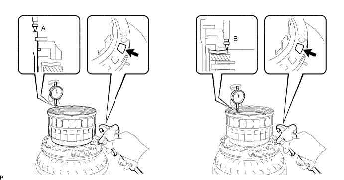
Using a dial gauge, measure the reverse clutch piston stroke (distance A) and the moving distance (distance B) of the reverse flange at both ends across a diameter while blowing air (392 kPa, 4 kgf/cm2, 57 psi) from the oil hole as shown in the illustration, and calculate the average.
Standard pack clearance 0.5 to 0.8 mm (0.020 to 0.031 in.) Note
Install a standard flange (3.3 mm (0.130 in.)) when measuring the moving distance (shaded area in the illustration.)
Tech Tips
Piston stroke A = 1.05 to 2.15 mm (0.041 to 0.085 in.)
Flange moving distance B = 0.72 to 1.08 mm (0.029 to 0.043 in.)
Pack clearance = Piston stroke A - Flange moving distance B - 0.06 mm (0.002 in.)
-
If the pack clearance is not within the standard, select and install a clutch flange that makes the pack clearance within the standard.
Standard flange thickness No. Thickness No. Thickness 0 2.8 mm (0.110 in.) 6 3.4 mm (0.134 in.) 1 2.9 mm (0.114 in.) 7 3.5 mm (0.138 in.) 2 3.0 mm (0.118 in.) 8 3.6 mm (0.142 in.) 3 3.1 mm (0.122 in.) 9 3.7 mm (0.146 in.) 4 3.2 mm (0.126 in.) A 3.8 mm (0.150 in.) 5 3.3 mm (0.130 in.) - -
-
-
REMOVE REVERSE CLUTCH REACTION SLEEVE
-
Using a screwdriver, remove the snap ring from the clutch drum assembly.
-
Remove the reverse clutch reaction sleeve, clutch cushion plate, reverse clutch flange, 5 reverse clutch discs, and 4 clutch plates from the reverse clutch hub sub-assembly.
-
-
INSTALL FORWARD CLUTCH PISTON
-
Coat 2 new O-rings with ATF, and install them on the No. 1 forward clutch piston.
-
-
INSTALL NO. 1 CLUTCH BALANCER
-
Coat a new O-ring with ATF and install it on the clutch balancer.
-
Install the No. 1 clutch balancer and forward clutch return spring sub-assembly.
Note
Be careful not to damage the O-ring.
-
Place SST on the No. 1 clutch balancer, and compress the return spring with a press.
Note
Stop pressing when the spring sheet is lowered to the place 1 to 2 mm (0.039 to 0.078 in.) from the snap ring groove to prevent the spring sheet from being deformed.
- SST
- 09350-30020 ( 09350-07040, 09350-07070 )
-
Install the snap ring with a snap ring expander.
Note
Do not expand the snap ring excessively.
-
Set the end gap of the snap ring in the piston as shown in the illustration.
Note
Be sure the end gap of the snap ring is not aligned with the spring retainer claw.
-
-
INSTALL FORWARD MULTIPLE DISC CLUTCH DISC
-
Install the 2 flanges, 6 discs and 5 plates to the input shaft.
Install in order F- D - P - D - P - D - P - D - P - D - P - D - F -
Using a screwdriver, install the hole snap ring.
Tech Tips
F = Flange
P = Plate
D = Disc
-
-
INSTALL INPUT SHAFT OIL SEAL RING
-
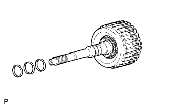
Coat the 3 oil seal rings with ATF.
-
Squeeze the ends of the 3 oil seal rings together, and then install them to the starter shaft groove.
Note
Do not over-spread the ring ends.
Tech Tips
After installing the oil seal rings, check that they rotate smoothly.
-
-
INSPECT PACK CLEARANCE OF FORWARD CLUTCH
-
Using a dial gauge, measure the moving distance (distance A) of the clutch flange at both ends across a diameter while blowing air from the oil hole as shown in the illustration, and calculate the average.
Standard pack clearance 0.6 to 0.9 mm (0.024 to 0.354 in.) Note
Install a standard flange (3.4 mm (0.134 in.)) when measuring the moving distance (shaded area in the illustration.)
Tech Tips
Flange moving distance A = 0.26 to 1.36 mm (0.010 to 0.054 in.)
Pack clearance = Flange moving distance A to 0.01 mm (0.0003 in.)
-
If the pack clearance is not within the standard, select and install a clutch flange that makes the pack clearance within the standard.
Standard flange thickness No. Thickness No. Thickness 0 3.0 mm (0.118 in.) 6 3.6 mm (0.142 in.) 1 3.1 mm (0.122 in.) 7 3.7 mm (0.146 in.) 2 3.2 mm (0.126 in.) 8 3.8 mm (0.150 in.) 3 3.3 mm (0.130 in.) 9 3.9 mm (0.154 in.) 4 3.4 mm (0.134 in.) A 4.0 mm (0.158 in.) 5 3.5 mm (0.138 in.) - -
-
-
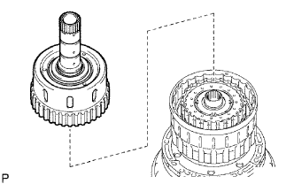
INSTALL INPUT SHAFT ASSEMBLY
-
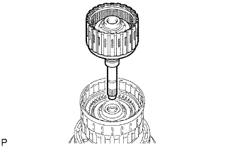
Install the input shaft assembly to the clutch drum.
-
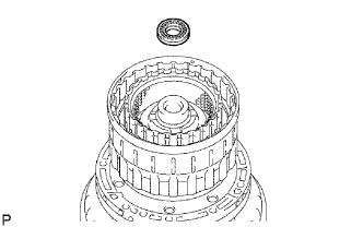
Install the thrust needle roller bearing to the clutch drum assembly.
Standard thrust needle roller bearing diameter Item Inside Outside Thrust needle roller bearing 21.3 mm (0.839 in.) 41.1 mm (1.618 in.)
-
-
INSTALL MULTIPLE DISC CLUTCH HUB
-
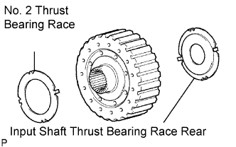
Install the No. 2 thrust bearing race and input shaft thrust bearing race rear to the multiple disc clutch hub.
Standard bearing and race diameter Item Inside Outside No. 2 thrust bearing race 38.4 mm (1.512 in.) 63.0 mm (2.480 in.) Input shaft thrust bearing race RR 22.6 mm (0.890 in.) 60.0 mm (2.362 in.) -
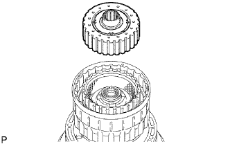
Install the multiple disc clutch hub to the clutch drum assembly.
-
-
INSTALL FORWARD CLUTCH HUB SUB-ASSEMBLY
-
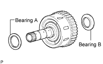
Install the 2 thrust needle roller bearings to the forward clutch hub sub-assembly.
Bearing and race diameter Item Inside Outside Bearing A 42.5 mm (1.673 in.) 61.2 mm (2.409 in.) Bearing B 33.3 mm (1.311 in.) 56.6 mm (2.228 in.) -
Install the forward clutch hub sub-assembly to the clutch drum assembly.
-
-
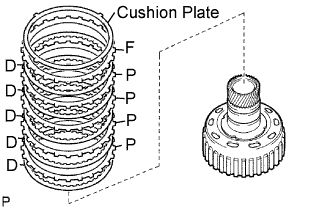
INSTALL REAR CLUTCH DISC
-
Install the 5 discs, 4 plates, flange and cushion plate to the reverse clutch hub.
Install in order D - P - D - P - D - P - D - P - D - F Tech Tips
D = Disc
P = Plate
F = Flange
-
-
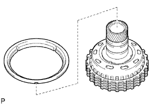
INSTALL REVERSE CLUTCH REACTION SLEEVE
-
Install the reverse clutch reaction sleeve to the reverse clutch hub.
-
-
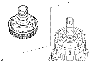
INSTALL REVERSE CLUTCH HUB SUB-ASSEMBLY
-
Install the reverse clutch hub sub-assembly, reverse clutch reaction sleeve, clutch cushion plate, reverse clutch flange, 5 reverse clutch discs, and 4 clutch plates to the clutch drum assembly.
-
Using a screwdriver, install the snap ring on the clutch drum and input shaft assembly.
-