CLUTCH DRUM AND INPUT SHAFT ASSEMBLY INSPECTION

-
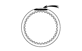
INSPECT REAR CLUTCH DISC
-
Replace all discs if one of the following problems is present: 1) a disc, plate or flange is worn or burnt, 2) the lining of a disc is peeled off or discolored, or 3) grooves or printed numbers have even a little bit of damage.
Note
Before assembling new discs, soak them in ATF for at least 15 minutes.
-
-
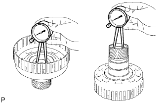
INSPECT REVERSE CLUTCH HUB SUB-ASSEMBLY
-
Using a dial indicator, measure the inside diameter of the reverse clutch hub bushing.
Standard inside diameter 35.812 to 35.837 mm (1.4099 to 1.4109 in.) Maximum inside diameter 35.887 mm (1.4129 in.)
-
If the inside diameter is greater than the maximum, replace the reverse clutch hub.
-
-
-
INSPECT FORWARD CLUTCH HUB SUB-ASSEMBLY
-
Using a dial indicator, measure the inside diameter of the forward clutch hub bushing.
Standard inside diameter 26.037 to 26. 062 mm (1.0251 to 1.0261 in.) Maximum inside diameter 26.112 mm (1.028 in.)
-
If the inside diameter is greater than the maximum, replace the forward clutch hub.
-
-
-
INSPECT FORWARD MULTIPLE DISC CLUTCH DISC
-
Replace all discs if one of the following problems is present: 1) a disc, plate or flange is worn or burnt, 2) the lining of a disc is peeled off or discolored, or 3) grooves or printed numbers have even a little bit of damage.
Note
Before assembling new discs, soak them in ATF for at least 15 minutes.
-
-
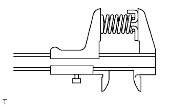
INSPECT FORWARD CLUTCH RETURN SPRING SUB-ASSEMBLY
-
Using a vernier caliper, measure the free length of the spring together with the spring seat.
Standard free length 26.74 mm (1.053 in.)
-
-
INSPECT DIRECT CLUTCH DISC
-
Replace all discs if one of the following problems is present: 1) a disc, plate or flange is worn or burnt, 2) the lining of a disc is peeled off or discolored, or 3) grooves or printed numbers have even a little bit of damage.
Note
Before assembling new discs, soak them in ATF for at least 15 minutes.
-
-
INSPECT REVERSE CLUTCH RETURN SPRING SUB-ASSEMBLY
-
Using a vernier caliper, measure the free length of the spring together with the spring seat.
Standard free length 21.04 mm (0.828 in.)
-
-
INSPECT DIRECT CLUTCH RETURN SPRING SUB-ASSEMBLY
-
Using a vernier caliper, measure the free length of the spring together with the spring seat.
Standard free length 19.51 mm (0.768 in.)
-
-
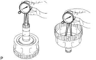
INSPECT PACK CLEARANCE OF DIRECT CLUTCH
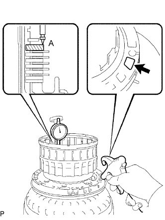
-
Using a dial gauge, measure the moving distance (distance A) of the clutch flange at both ends across a diameter while blowing air from the oil hole as shown in the illustration, and calculate the average.
Standard pack clearance 0.5 to 0.8 mm (0.020 to 0.031 in.) Note
Install a standard flange (3.4 mm (0.134 in.)) when measuring the moving distance (shaded area in the illustration).
Tech Tips
Flange moving distance A = 0.26 to 1.14 mm (0.010 to 0.045 in.)
Pack clearance = Flange moving distance A - 0.05 mm (0.002 in.)
-
If the pack clearance is not within the standard, select and install a clutch flange that makes the pack clearance within the standard.
Standard flange thickness No. Thickness No. Thickness 0 3.0 mm (0.118 in.) 5 3.5 mm (0.138 in.) 1 3.1 mm (0.122 in.) 6 3.6 mm (0.142 in.) 2 3.2 mm (0.126 in.) 7 3.7 mm (0.146 in.) 3 3.3 mm (0.130 in.) 8 3.8 mm (0.150 in.) 4 3.4 mm (0.134 in.) - -
-
-
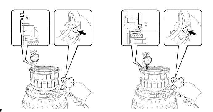
INSPECT PACK CLEARANCE OF REVERSE CLUTCH
-
Using a dial gauge, measure the reverse clutch piston stroke (distance A) and the moving distance (distance B) of the reverse flange at both ends across a diameter while blowing air (392 kPa, 4 kgf/cm2, 57 psi) from the oil hole as shown in the illustration, and calculate the average.
Standard pack clearance 0.5 to 0.8 mm (0.020 to 0.031 in.) Note
Install a standard flange (3.3 mm (0.130 in.)) when measuring the moving distance (shaded area in the illustration.)
Tech Tips
Piston stroke A = 1.05 to 2.15 mm (0.041 to 0.085 in.)
Flange moving distance B = 0.72 to 1.08 mm (0.029 to 0.043 in.)
Pack clearance = Piston stroke A - Flange moving distance B - 0.06 mm (0.002 in.)
-
If the pack clearance is not within the standard, select and install a clutch flange that makes the pack clearance within the standard.
Standard flange thickness No. Thickness No. Thickness 0 2.8 mm (0.110 in.) 6 3.4 mm (0.134 in.) 1 2.9 mm (0.114 in.) 7 3.5 mm (0.138 in.) 2 3.0 mm (0.118 in.) 8 3.6 mm (0.142 in.) 3 3.1 mm (0.122 in.) 9 3.7 mm (0.146 in.) 4 3.2 mm (0.126 in.) A 3.8 mm (0.150 in.) 5 3.3 mm (0.130 in.) - -
-
-
INSPECT PACK CLEARANCE OF FORWARD CLUTCH
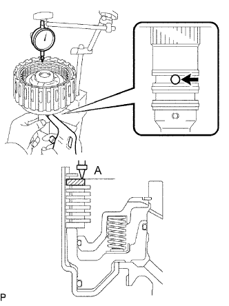
-
Using a dial gauge, measure the moving distance (distance A) of the clutch flange at both ends across a diameter while blowing air from the oil hole as shown in the illustration, and calculate the average.
Standard pack clearance 0.6 to 0.9 mm (0.024 to 0.354 in.) Note
Install a standard flange (3.4 mm (0.134 in.)) when measuring the moving distance (shaded area in the illustration.)
Tech Tips
Flange moving distance A = 0.26 to 1.36 mm (0.010 to 0.054 in.)
Pack clearance = Flange moving distance A to 0.01 mm (0.0003 in.)
-
If the pack clearance is not within the standard, select and install a clutch flange that makes the pack clearance within the standard.
Standard flange thickness No. Thickness No. Thickness 0 3.0 mm (0.118 in.) 6 3.6 mm (0.142 in.) 1 3.1 mm (0.122 in.) 7 3.7 mm (0.146 in.) 2 3.2 mm (0.126 in.) 8 3.8 mm (0.150 in.) 3 3.3 mm (0.130 in.) 9 3.9 mm (0.154 in.) 4 3.4 mm (0.134 in.) A 4.0 mm (0.158 in.) 5 3.5 mm (0.138 in.) - -
-